


Manipulator workflow: URDF to pick and place#
Use this workflow to take a manipulator and end effector from a Unified Robot Description Format (URDF) source to a validated pick-and-place task. The workflow connects the detailed robot setup, gain tuning, motion generation, and ROS 2 tutorials without repeating them.
Complete Stages 1–7 in order. Complete the optional ROS 2 stage only when the application requires it. At each stage, satisfy the checkpoint before you continue. If a checkpoint fails, use the troubleshooting table to identify the layer that needs attention before you change planner parameters.
Learning objectives#
By the end of this workflow, you can:
Import and assemble a manipulator and end effector.
Validate joint drives, limits, gains, and direct articulation control.
Validate the robot description and frame definitions against the assembled robot.
Select and configure a planner, controller, trajectory executor, and task orchestrator.
Run and validate a physics-backed pick-and-place task against measurable success criteria.
Choose between native Isaac Sim control, the ROS 2 Bridge, and in-process
ros2_control.Diagnose failures at the asset, actuation, kinematics, planning, execution, grasping, or ROS 2 layer.
Prerequisites#
Complete the beginner-level wheeled robot tutorials in Robot Setup Tutorials Series.
Obtain the manipulator URDF and every mesh that it references.
Obtain the end-effector URDF or USD asset and its attachment transform.
Choose task acceptance gates before tuning or running a planner. If the project does not already define them, begin with the example values in Choose validation gates.
Prepare the input assets#
Before Stage 1, make the source files self-contained and physically usable:
Expand Xacro or other macros to URDF. The importer consumes the resulting URDF, not the macro source.
Make every
package://or relative mesh URI resolvable on the machine running Isaac Sim. Keep the mesh packages with the URDF, or add the package mappings described in URDF Importer configuration options.Check that dimensions use meters, revolute limits use radians, and each actuated joint declares an axis, lower and upper limits, effort, and velocity. Each dynamic link needs positive mass and valid inertia.
Confirm that visual and collision meshes appear at the same scale and orientation. Prefer simpler collision meshes when detailed render geometry produces unstable or expensive contact.
For a separate end effector, identify its root link, controllable joint, mimic joints, open and closed positions, and attachment frame. For a USD end effector, record the equivalent prim paths and joint names.
Record the fixed transform from the manipulator flange to the end-effector root. If it is not supplied by the manufacturer, place the two frames in a common CAD or USD view and measure the translation and rotation.
The assets are ready when each imports without missing meshes, the link and joint hierarchy is complete, and the expected dimensions and joint limits are visible. See URDF conventions for importer coordinate and joint conventions.
Choose validation gates#
Use hardware requirements or application requirements when they are known. Otherwise, the following values are practical starting gates for a tabletop simulation. They are examples, not universal robot specifications; tighten or relax them for the robot, object scale, and task risk, then record the chosen values with every validation run.
Measurement |
Starting gate |
How to apply it |
|---|---|---|
Arm joint tracking |
Maximum error |
Check every commanded arm joint after the motion settles. |
Tool pose at grasp |
Position |
Measure the physical grasp point, not only the flange frame. |
Lift and hold |
|
Require continuous clearance and no loss of the grasp. |
Object drift during transport |
Position |
Measure from the object pose captured when the grasp closes. |
Placement |
Position |
Compare the settled object pose with the requested place pose. |
Settled object |
Linear velocity |
Start the hold interval only after both velocity limits are met. |
Phase timeout |
Arm motion |
Treat a timeout as a failed gate instead of advancing the task. |
Attention
Optional Stage 8 offers several ROS 2 paths. The linked MoveIt 2 tutorial requires a Linux ROS 2 environment. Other ROS 2 workflows can use Pixi-managed ROS 2 Jazzy on Windows; follow the platform requirements in each linked tutorial.
Important
Reference-robot scope: The four manipulator-series tutorials and the runnable pick-and-place scripts use a UR10e with a Robotiq 2F-140 gripper. Other linked component tutorials can show different robots. For another robot, derive its limits, gains, frames, controller configuration, and task poses from that robot; supplying a different URDF or XRDF alone does not adapt the scripts. Complete Custom-robot adaptation before running them with another robot.
Workflow at a glance#
Stage |
Goal |
Primary guidance |
Continue when |
|---|---|---|---|
1 |
Import and assemble the robot. |
The articulation and gripper load without unstable motion. |
|
2 |
Configure physics and joints. |
Joint names, limits, drives, and effort limits are correct. |
|
3 |
Tune and stress-test the drives. |
The robot tracks targets and remains stable under the intended load. |
|
4 |
Validate the robot description and frames. |
Controlled joints, joint mappings, and motion frames match the assembled robot. |
|
5 |
Select and configure the motion and execution stack. |
Stage 5: Select and configure the motion and execution stack |
The native stack is configured, and any ROS 2 planning inputs are identified for Stage 8. |
6 |
Validate the selected components independently. |
The applicable direct-control, motion, and execution tests pass. |
|
7 |
Run and validate pick-and-place. |
Part 4 of Tutorial 9: Pick and Place Example |
Grasp, lift, transport, release, and placement checks pass. |
8 (optional) |
Add ROS 2 when required. |
Direct ROS 2 control works before planning through MoveIt 2. |
Stage 1: Import and assemble the robot#
Follow Tutorial 6: Setup a Manipulator to import the manipulator and end effector.
Inspect the imported assets before assembly. Record the arm joints, gripper command joint, mimic joints, base link, flange, end-effector root, and intended tool frame.
Configure mimic joints and gripper limits before you attach the gripper.
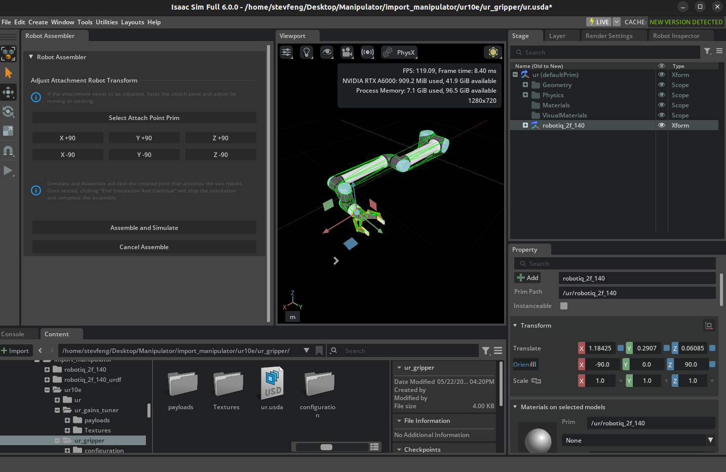
Use the Robot Assembler to connect the end effector to the manipulator.
Normalize the assembled articulation:
Keep one
UsdPhysics.ArticulationRootAPIon the assembled robot. If an attached articulated end effector retains a subordinate articulation root, remove the Articulation Root API from that prim without removing its rigid-body or joint schemas.For an articulated end effector, confirm that the fixed joint connects the flange and end-effector root to the same joint hierarchy.
Confirm that a fixed-base manipulator remains attached to the world.
Align the end effector. Select the intended flange and attachment frames in Robot Assembler, apply the manufacturer-provided fixed transform, and inspect the result from multiple viewpoints. Correct the assembly transform or fixed joint instead of moving the visual meshes independently.
Create a name mapping from the source robot descriptions to the final USD asset. Include every controlled arm joint, the gripper command joint, the base link, the flange, and the tool frame. Record changed names; do not depend on DOF indices remaining unchanged after assembly.
Review collision filtering after assembly. The standard Robot Assembler workflow does not automatically create filtered pairs between assembled components. Use Robot Self-Collision Detector to inspect internal pairs, including mimic-coupled gripper links, and inspect any existing filters. For each pair that is expected to overlap without generating contact, enable Filtered Pair to explicitly author a
UsdPhysics.FilteredPairsAPIrelationship. Confirm that every intentional filter persists in the saved asset. Correct the alignment or collision geometry for an unintended overlap. Keep collisions with task objects and the environment enabled.Press Play, stop the timeline, and reset the stage several times.
Note
If the end effector uses suction or magnetic attachment rather than mechanical fingers, follow Setting up a Surface Gripper before step 4. Author a D6 joint at each contact point, create the Surface Gripper prim with Create > Robots > Surface Gripper, and set Attachment Points to the D6 joint. Set Max Grip Distance for contact acceptance. Tune Shear Force Limit and Coaxial Force Limit when the attachment must match a hardware force envelope.
Important
Checkpoint: The robot remains assembled, its links do not separate or explode, and the gripper follows the flange. Resolve articulation-root, attachment, collision, and unit problems before you tune drives.
Stage 2: Configure physics and direct control#
For the supplied UR10e and Robotiq 2F-140 asset, complete these steps from Tutorial 7: Configure a Manipulator in order. The tutorial includes the exact prim selections and UI captures:
Adjust the UR10e articulation: author the PhysX articulation on
ur/Geometry/World, set solver position iterations to64and velocity iterations to4, then set the sleep threshold to0.00005and stabilization threshold to0.00001.Add gripper physics materials: set static and dynamic friction to
1.0on the reference material and bind it to both inner-finger colliders.Configure the gripper effort limit: set
finger_jointMax Force to200for the supplied asset.Inspect the assembled articulation: refresh the articulation in Physics Inspector and verify that the measured DOF position follows the target.
These numbers are reference settings for the supplied asset, not defaults for every manipulator. For another robot, start from its manufacturer limits and inspect these properties:
Joint type, axis, lower limit, and upper limit.
Position or velocity drive configuration.
Stiffness, damping, maximum force, and maximum joint velocity.
Link mass, inertia, collision geometry, and self-collision behavior.
Physics timestep and solver settings used by the final application.
Use Articulation Controller to command one arm joint at a time. Then run Part 1 of Tutorial 9: Pick and Place Example to open and close the reference gripper independently. Direct commands isolate the asset and actuator layer from inverse kinematics (IK) and motion planning.
Important
Checkpoint: Every commanded joint moves in the expected direction, stops at its limit, and reports a matching position. The gripper closes and opens without moving unrelated arm joints.
Stage 3: Tune and validate joint gains#
Note
This stage uses Tutorial 11: Tuning Joint Drive Gains, which is listed under the Advanced Level in this series. Complete it now and return to continue with Stage 4.
Complete Tutorial 11: Tuning Joint Drive Gains before you test a motion planner. Tune with the same payload, physics timestep, solver settings, effort limits, and velocity limits as the final Stage 7 pick-and-place scene. This does not mean to use the defaults unless the final scene intentionally uses them. Attach the intended gripper and a representative payload while tuning; if payload mass varies, validate the heaviest planned payload.
Test |
What it reveals |
Required result |
|---|---|---|
Zero-gain observation |
Confirms whether the imported joints have active drives. |
The observed response agrees with the authored drive configuration. |
Snap to Limits |
Exposes insufficient stiffness, damping, maximum force, or unreachable limits. |
Every required joint passes or has a documented collision-limited range. |
Step Function |
Shows overshoot, settling time, and steady-state error. |
Tracking meets the task’s accuracy and settling requirements. |
Sinusoidal |
Shows lag and tracking quality across repeated motion. |
The joint tracks the target across the expected application bandwidth. |
Stress: Random Walk |
Tests stability across independent joint targets. |
All required joints remain stable with velocity limits enabled. |
Stress: Adversarial |
Tests difficult correlated configurations. |
No instability, growing oscillations, or NaN values occur. |
Payload hold and transport |
Tests gravity compensation and tracking with the real tool and payload. |
The arm holds and transports the payload without unacceptable drift. |
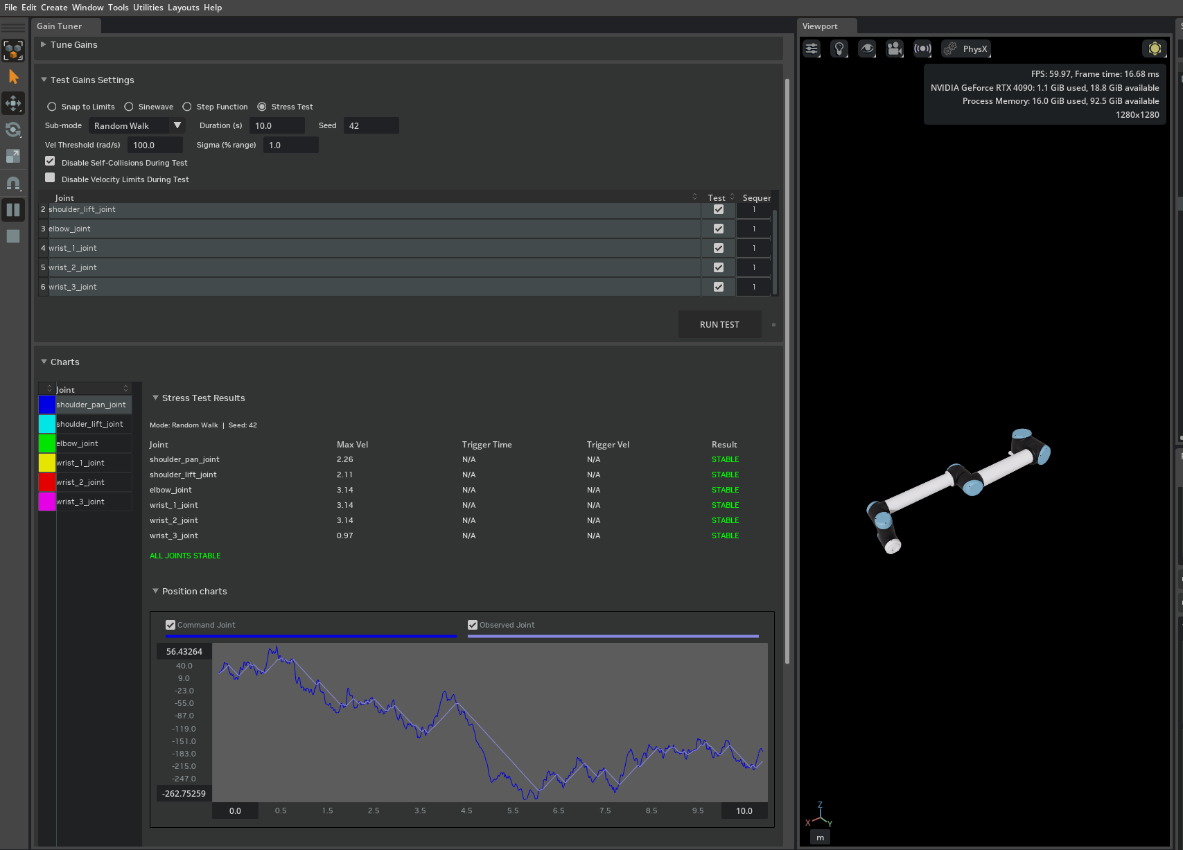
Treat Fail and Blocked differently in the Gain Tuner. A failure usually indicates a tracking or actuator problem. A blocked result can indicate that collision geometry prevents the authored joint limit from being reached. Use Disable Self-Collisions only as a diagnostic; if the test then passes, tighten the joint limit or correct the collision geometry instead of increasing the gains.
Record the final stiffness, damping, maximum force, velocity limit, test parameters, physics timestep, solver settings, end-effector mass, and payload.
Important
Checkpoint: The robot passes the tracking and stability tests without exceeding the intended actuator or velocity envelope.
Stage 4: Validate the robot description and frames#
Before selecting a motion stack, record and validate the joint and frame definitions that every option must match. Treat the final assembled USD asset as the source of truth, not an earlier manipulator-only asset. If a motion component consumes a URDF, confirm that the URDF represents the controlled kinematic chain and contains every frame that the component uses.
Check these items:
Each controlled joint in the robot description has a matching name, matching limits, and a matching axis in the USD articulation.
Any difference between the robot description’s joint order and the USD articulation order has an explicit name-based mapping.
The base frame matches the USD articulation root transform.
The flange and intended tool frame exist on the assembled kinematic chain.
The physical grasp point is measured relative to the tool frame. For a parallel-jaw gripper, use the closed-finger center; for suction, use the attachment point.
The transforms between the base, flange, tool frame, and physical grasp point use the expected units and orientation convention.
Resolve discrepancies in the robot description or an explicit name mapping instead of renaming prims in a referenced asset.
Important
Imported-manipulator readiness checkpoint: Before you select a motion stack, confirm all of the following:
The Stage 1–3 checkpoints pass after you save and reopen the asset.
The final USD asset has one connected articulation for the manipulator and any articulated end-effector joints, with the intended flange-to-end-effector transform.
The robot description resolves every required joint, link, and task frame against the final USD asset. Direct commands reach the expected named DOFs through every applicable command field.
Only intentional internal collision pairs are filtered, and collisions with task objects and the environment remain enabled.
Do not begin motion-generation integration until every applicable item passes.
Stage 5: Select and configure the motion and execution stack#
Note
In the table below and in Tutorial 9: Pick and Place Example, mg refers
to isaacsim.robot_motion.experimental.motion_generation. This module
carries the experimental namespace; its API may change between releases.
The word controller can refer to several layers. Select one option at each required layer instead of treating every API as an interchangeable planner. Add the optional ROS 2 layer in Stage 8 only when the application requires it.
Layer |
Option |
Use it when |
Output or responsibility |
|---|---|---|---|
Task orchestration |
Inline phases, finite-state machine, or behavior tree. |
The task sequences approach, grasp, recovery, and placement behavior. For behavior tree patterns, see Behavior tree with py_trees or Behavior tree with Omniverse Behavior Tree. |
Selects the next motion or gripper action. |
Reactive motion |
cuMotion |
Track changing targets. Use RMPflow for obstacle-aware GPU motion or PINK for CPU-based weighted IK on Linux x86_64. |
Desired joint state on every control step. |
Global motion |
cuMotion |
Find a collision-free route or optimize a constrained trajectory before execution. |
|
Time parameterization |
cuMotion |
Convert known paths or waypoints into smooth, time-optimal motion. |
|
Trajectory execution |
|
A native planner or generator produced an |
Samples the trajectory and produces desired joint state. |
ROS 2 planning |
MoveIt 2. |
A ROS 2 planning pipeline must own motion planning. |
Joint trajectory sent through the Bridge or |
Low-level actuation |
Articulation API, Articulation Controller, or |
Joint targets must reach the PhysX articulation drives. |
Applies position, velocity, or effort commands. |
Configure the selected option#
Complete only the configuration that the selected motion option requires:
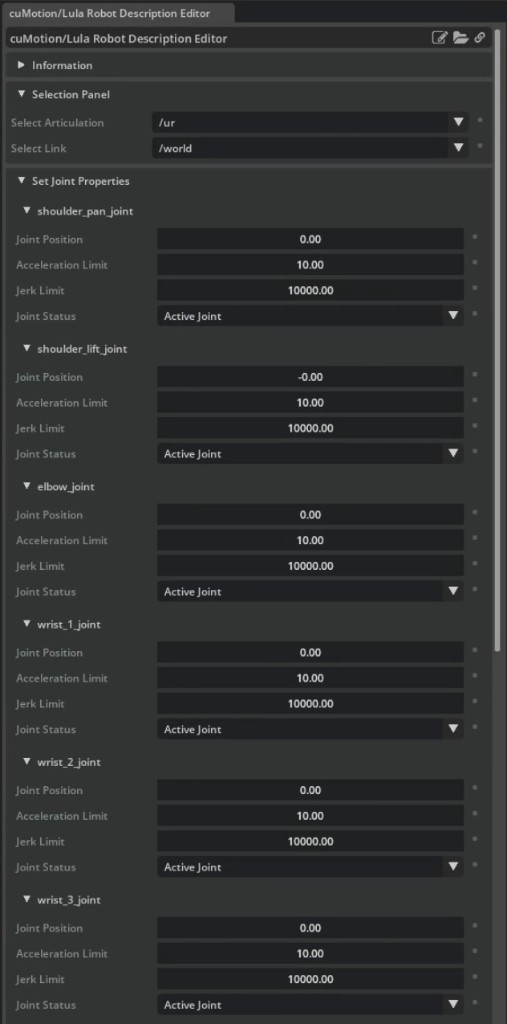
cuMotion: Follow Tutorial 8: Generate Robot Configuration File to export the assembled robot to URDF and generate its XRDF. Confirm that the XRDF defines the controlled joints, default configuration, and tool frame required by cuMotion. Confirm that the selected XRDF tool frame, such as
tool0, corresponds to the physical end-effector mount in the assembled USD. Record the transform from that frame to the physical grasp point.PINK: Load a URDF that contains the controlled joints and selected tool frame. The URDF does not need to include gripper links controlled separately through the USD articulation, and an XRDF is not required. Build the optional collision model from the URDF and supply SRDF collision exclusions only when using collision barriers. See Robot Configuration Tutorial.
MoveIt 2: Defer setup to Stage 8. MoveIt 2 consumes the robot description supplied by the selected ROS 2 path, along with its SRDF, planning groups, and controller configuration. It does not use the XRDF.
Direct joint control or trajectory execution: Use the USD articulation and its joint mapping. No separate motion-model file is required when no kinematics or planning component consumes one.
If you select a collision-aware cuMotion option, such as RMPflow,
GraphBasedMotionPlanner, or TrajectoryOptimizer, verify that its
collision spheres cover the arm and attached end effector without large gaps
or excessive inflation. Validate the XRDF and self-collision rules against the
final assembled USD asset. TrajectoryGenerator does not perform collision
avoidance by itself, so it does not require this collision-sphere check.
Use the following detailed tutorials for maintained native motion options:
RMPflow for reactive, obstacle-aware target following.
Graph-Based Motion Planner for collision-free sampling-based paths.
Trajectory Optimizer for collision-free optimized trajectories.
Trajectory Generator for time-optimal motion from known waypoints or path specifications.
PINK IK Controller for CPU-based reactive IK.
For advanced composition, use
Controller composition to combine, chain,
or switch BaseController implementations. Use
Robot Poser to author or replay named joint poses. Neither
option is a complete collision-aware task planner.
The complete UR10e examples in Part 4 of Tutorial 9: Pick and Place Example use
cuMotion RMPflow and PINK. The Graph-Based Motion Planner, Trajectory Optimizer,
and Trajectory Generator tutorials are component demonstrations;
they do not provide drop-in versions of the same pick-and-place task. These
components produce an mg.Path or mg.Trajectory object. Convert the
result to joint commands with mg.TrajectoryFollower, and supply a task
policy that invokes the planner for each motion segment and handles gripper
actions between segments.
Start with inline phases for a linear task, then use a finite-state machine or behavior tree when the task needs recovery, retries, interrupts, or coordination. See State Machines for Robot Behavior.
Note
For new work, use the current options above. The
isaacsim.robot_motion.lula and
isaacsim.robot_motion.motion_generation APIs are legacy paths for
maintaining older applications. Custom Jacobian-based differential IK and
direct RobotPoser kinematics are advanced building blocks, not complete
collision-aware task planners.
Important
Checkpoint: You have identified one option at each layer — task policy, planner or reactive controller, executor, and low-level actuation path. Configure each selected native component with the Stage 4 joint and frame definitions, and confirm that the planner’s output type matches the executor’s expected input. For an optional ROS 2 planning layer, record the required robot description, planning configuration, and controller inputs for Stage 8. For a collision-aware option, confirm that its collision representation moves with every link.
Stage 6: Validate the selected components independently#
Start with direct articulation and gripper control, then test only the motion and execution components selected in Stage 5. Parts 1–3 of Tutorial 9: Pick and Place Example provide the reference tests for the supplied UR10e asset.
Adapt the examples for an imported or custom robot#
The standalone pick-and-place scripts instantiate the supplied UR10e USD and
contain UR10e-specific names and poses. In the cuMotion example,
--xrdf-dir changes the motion-library robot description. In the PINK
example, --urdf changes the kinematic model. Neither option replaces the
simulated USD articulation or the remaining UR10e-specific values. Complete
this adaptation even when the imported asset is another version of the UR10e.
Before you use the scripts with an imported asset, adapt and verify:
The robot USD reference and
_ROBOT_PRIM_PATH.The ordered arm-joint names,
_GRIPPER_JOINT, and gripper command or attachment interface._EE_LINK_NAME, the selected tool frame,_TOOL_OFFSET, and the physical grasp offset.The initial posture, tool orientation, pick pose, place pose, and workspace clearances.
The gripper open and closed targets, mimic behavior, and force limits.
The selected robot description and any collision representation against the same assembled USD asset.
The controller output applied on each step. Forward each available position, velocity, and effort field to its corresponding named DOF. For a Newton-authored articulation, verify that required velocity targets reach the arm actuators instead of assuming that position targets are sufficient.
Note
The reference cuMotion pick-and-place script applies desired joint positions
only. If the selected actuator interface also requires controller velocity
targets, apply desired.joints.velocities using
desired.joints.velocity_indices. Do not synthesize velocity targets when
the controller does not provide them.
Validate the selected path#
Selected component |
Test |
Required result |
|---|---|---|
Direct articulation and gripper control |
Run Part 1 of Tutorial 9: Pick and Place Example, or the adapted equivalent, and command every required arm and gripper joint directly. |
Joint selection, direction, limits, mimic behavior, and gripper state are correct. |
|
Run Part 2 with a known collision-free joint-space trajectory. |
The executor starts from the expected state and tracks within the defined joint tolerance without timing out. |
cuMotion RMPflow |
Run Part 3 first without an obstacle and then with an obstacle. |
Tool-frame tracking and world synchronization remain within the defined tolerances. |
PINK |
Follow IK Controller Tutorial and test a nearby, nonsingular target before targets near joint limits. |
The solver reaches the target without violating joint limits or changing to an unacceptable posture. |
cuMotion global planner or trajectory generator |
Run the selected detailed tutorial and execute its output with the selected trajectory executor. |
Planning returns the expected |
Important
Checkpoint: Every applicable component test passes separately. Do not begin a complete task while direct control, trajectory execution, tool-frame tracking, or world synchronization is failing.
Stage 7: Run and validate pick-and-place#
Run the cuMotion RMPflow or PINK example in Part 4 of Tutorial 9: Pick and Place Example for the UR10e reference path, or run the adapted task from Stage 6. A typical task contains these phases:
Move above the pick pose.
Descend to the grasp pose.
Close or attach the gripper.
Lift and confirm that the object leaves the support.
Transport above the place pose.
Descend to the release pose.
Open or detach the gripper.
Retreat and allow the object to settle.
Validate the object, not only the end-effector target. Use the acceptance criteria defined in Prerequisites for every run.
Note
Before running the task, confirm that the pick target has a Rigid Body API, collision geometry suitable for a dynamic rigid body, and task-appropriate mass and inertia. Bind a Physics Material when the task requires friction values other than the PhysX defaults.
Attention
The Part 4 scripts demonstrate motion sequencing. They test tool or gripper convergence, advance after a phase timeout, and do not evaluate the object’s lift, hold, or settled placement. Reaching the final phase is therefore not a validated success. Add object-state checks to the application or record the measurements independently, and stop at the first failed gate.
Gate |
Measured pass condition |
Failure usually belongs to |
|---|---|---|
Grasp |
The gripper reports the expected state, and the object is within the defined position and orientation tolerance of the grasp frame. |
Frames, IK, gripper joints, contact, attachment configuration, or object rigid-body properties (mass, friction, collision geometry). |
Lift and hold |
The object remains above the minimum lift height for the defined hold duration without exceeding the drift or velocity limits. |
Gripper force, friction, payload tuning, or grasp offset. |
Transport |
The object remains within the grasp tolerance while the arm follows the commanded route and maintains the required environment clearance. |
Tracking gains, acceleration, collision model, or world synchronization. |
Place and release |
The released object settles on the support within the task’s position and orientation tolerance, with linear and angular velocities below the settle limits. |
Place frame, release timing, support collision, or task policy. |
Use rigid-body pose and velocity readback for validation and retain the measured values with the run result. A tool can reach its target while the object slips, remains on the source support, or misses the place region. Treat a motion-phase timeout as a failure.
The cuMotion UR10e example excludes the pick object from its tracked obstacle set so the robot can approach and grasp it. Exclusion also removes payload-versus-environment collision checking. After grasping, represent the payload as attached collision geometry when the selected stack supports it. If it does not, document the missing collision coverage and use payload-aware robot collision geometry, conservative clearance, and constrained transport routes.
Clearly identify the grasp mechanism:
Use direct gripper-joint targets for a parallel-jaw gripper.
Use
SurfaceGripperfor authored suction or magnetic attachment behavior.Label a fixed-joint attachment as an assisted grasp.
For a strict contact-only task, do not move the object with pose writes, kinematic following, or a hidden attachment.
Important
Checkpoint: The object passes the grasp, lift, transport, and released-pose checks in the same run.
Stage 8 (optional): Add ROS 2 planning and control#
Important
Complete Stages 1–7 with native Isaac Sim control and satisfy the platform requirements listed in Prerequisites before this stage.
Add ROS 2 only after native direct-joint control passes. Choose one connection model:
Path |
Architecture |
Start with |
|---|---|---|
ROS 2 Bridge |
Publish joint states and receive commands through ROS 2 topics. MoveIt 2 and the controller run outside Isaac Sim. |
ROS 2 Joint Control: Extension Python Scripting, then MoveIt 2. |
In-process |
Host the standard Controller Manager inside Isaac Sim. Use a
trajectory controller directly or connect MoveIt 2 through its
|

For in-process ros2_control, the USD drive determines the command
interface:
Stiffness above zero selects a position command interface.
Damping without stiffness selects a velocity command interface.
A drive with neither gain selects an effort command interface.
A joint without a drive is state-only and cannot receive commands.
First command a known joint trajectory without MoveIt 2. If that succeeds,
add MoveIt 2 and verify joint names, joint order, planning groups, controller
names, and the FollowJointTrajectory action. When use_sim_time is
enabled, publish /clock. The Controller Manager update rate cannot exceed
the physics rate.
Important
Checkpoint: Joint-state feedback is current, a direct controller command moves the expected joints, and MoveIt 2 executes only after the direct ROS 2 control path passes.
Troubleshooting by layer#
Stop at the first failing checkpoint. Fix that layer before changing a later planner or task-policy layer.
Symptom |
Inspect first |
Corrective action |
|---|---|---|
Robot collapses when you press Play. |
Joint drives and gains. |
Confirm that required joints have drives, then complete the zero-gain and Snap to Limits workflow. |
Robot oscillates, moves violently, or produces NaN values. |
Gains, velocity limits, timestep, and solver settings. |
Reduce aggressive gains or targets, restore realistic velocity limits, and rerun the Stress tests. |
Snap to Limits reports Fail. |
Stiffness, damping, maximum force, and payload. |
Tune the actuator and confirm that maximum force does not cap the drive. |
Snap to Limits reports Blocked. |
Self-collision and authored joint limits. |
Diagnose with Disable Self-Collisions, then correct collision geometry or tighten the joint limit. |
A direct joint command moves the wrong joint or no joint. |
Articulation root, DOF names, and command indices. |
Address joints by the articulation’s reported names and verify that each commandable joint has a drive. |
IK fails in an empty scene. |
Base frame, tool frame, reachability, and joint limits. |
Visualize the commanded tool pose, verify frame names and units, and test a nearby nonsingular target. |
Motion succeeds without obstacles but fails with them. |
The selected collision representation and world synchronization. |
Correct the selected collision representation, update the robot-root transform, synchronize obstacle transforms, and reduce excessive obstacle inflation. For cuMotion, check collision-sphere coverage. |
Planning succeeds but trajectory tracking diverges. |
Initial state, drive tracking, trajectory clock, and control rate. |
Start from the planned state, reset the controller, pass absolute controller time, and rerun the gain tests at the execution timestep. |
The tool reaches the cube but the cube does not lift. |
Grasp frame, contact, mimic joints, force, friction, and object mass and collision geometry. |
Align the physical grasp point, validate gripper closure, confirm the selected grasp mechanism is active, and verify the object has non-zero mass and a physics material with friction. |
The held object causes avoidance or prevents placement. |
Target-object filtering and carried-payload collision coverage. |
Exclude the target during approach only when required. After grasping, use attached collision geometry when supported. Otherwise, document that the planner does not check payload-versus-environment collisions and enforce conservative payload-aware clearance. |
Native control works but ROS 2 control does not. |
Joint names, interfaces, controller state, and ROS graph. |
Follow the Stage 8 diagnostic sequence
(Stage 8 (optional): Add ROS 2 planning and control): list hardware interfaces
and controllers, verify |
MoveIt 2 plans but does not execute. |
Controller name and action endpoint. |
Confirm that the expected trajectory controller is active and exposes
the configured |
The first run appears to hang. |
Asset download and material compilation. |
Wait for asset and MDL loading to finish, then reproduce the controller problem after the scene is fully loaded. |
Completion checklist#
Before you reuse the robot in another manipulation task, confirm that:
The saved USD contains the intended articulation, end effector, physics properties, and drives.
Direct arm and gripper commands were validated before adding IK or planning.
Gain results include the tested payload, timestep, limits, and solver configuration.
The robot description, base frame, tool frame, and grasp point match the saved USD. When the selected stack uses collision avoidance, its collision representation also matches the saved USD.
The chosen planner produces the correct output type and uses the appropriate executor.
The task policy has convergence checks and timeouts for each phase.
Success comes from recorded object pose and velocity measurements after grasp, lift, and release, using the predefined tolerances and durations.
When ROS 2 is used, the ROS 2 joint names and command interfaces match the USD drives.