


Tutorial 10: Rig Closed-Loop Structures#
Some models are challenging to represent. Robots and grippers still have unique features and structures that are uncommon. In this document you learn some techniques to model these unique features and learn a general approach for managing these unique configurations.
Learning Objectives#
In this tutorial, you will:
Use USD Layers to edit and test assets
Add materials and adjust joints post CAD import
Break a closed loop articulation chain
Add joint drives, including mimic joints
Adjust collision shapes
Test grippers by building a test setup
30 Minutes Tutorial
Start with a Robotiq 2F-85 Parallel Gripper STP file imported into an Onshape document and with joints modeled. This tutorial does not directly cover tuning the joints. Instead, tuned parameters are provided when configuring the asset. To learn more about gains tuning see Tutorial 11: Tuning Joint Drive Gains and Gain Tuner Extension.
Getting Started#
Prerequisite
Complete the Isaac Sim Basics series to learn the basic core concepts of how to navigate inside NVIDIA Isaac Sim.
Complete the Assemble a Simple Robot and Adding Sensors and Cameras tutorials to learn the concepts of rigid body API, collision API, joints, drives, and articulations.
Optionally, read Onshape importer if you want to understand how the source asset was originally imported and rigged.
Note
The starting asset is located at Samples/Rigging/Gripper/Robotiq 2F-85/Robotiq_2F_85_edit.usdc. Open this file to begin the tutorial.
Rigging the Robot#
Using Layers to Edit and Test an Asset#
The starting asset contains the full robot structure with correct joint orientations and limits, but no physics drives or constraints applied. You must complete a few additional steps to make the asset fully functional.
Instead of editing the base asset directly, use layers. Layers allow building a scene on top of a root asset and saving changes without modifying the underlying file. For example, you can add a ground plane and objects used to test the gripper, save the testing setup in layers, while keeping the original gripper asset free of any extraneous items used for testing.
Open
Robotiq_2F_85_edit.usdcfrom theSamples/Rigging/Gripper/Robotiq 2F-85folder. This file already referencesRobotiq_2F_85_base.usdcas a sublayer, establishing the layer structure you need.
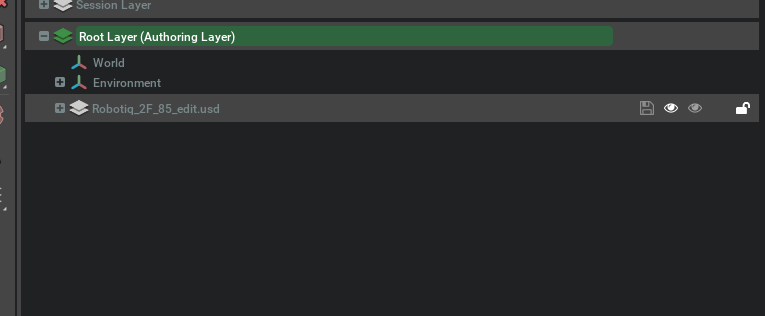
The Authoring layer is where changes are saved. To switch between layers, double-click on the choice. Ensure Robotiq_2F_85_edit.usdc is the active authoring layer before making any edits.
If changes are made in the wrong authoring layer, you can drag the prims with the delta between layers to merge them into the receiving layer.
This is how the joints were named for this asset:
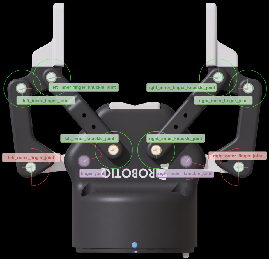
Note
If you re-import this asset from Onshape in the future, combine parts that make rigid bodies on Group Mates before importing to simplify the rigid bodies on stage (also useful for renaming the fingers to left_finger_... and right_finger_...).
Adjusting Joints Post Import#
Joint orientations, limits, and initial pose are pre-configured in Robotiq_2F_85_base.usdc. The robot root /Robotiq_2F_85 already has a 90° rotation around the Y axis applied. Positive rotation on finger_joint closes the gripper. No manual offset corrections are required.
Add fingertip physics material to increase the friction contact:
Open the Menu Create > Physics > Physics Material.
Select Rigid Body Material.
Rename the material to
fingertip_material.Set both friction coefficients to 0.8 (default rubber) and Friction Combine Mode
max.Select
right_inner_fingerandleft_inner_finger. In the Property tab, in Materials on selected models pick the created material.
Note
you may need to de-select instanceable for the two xforms in right/left_inner_finger, and set the physics materials on the mesh Defeatured_2F_85_PAD_OPEN_fingertipsstep directly.
Breaking the Articulation Loop#
If you try to simulate this asset now, you’ll get two big warnings on the screen:
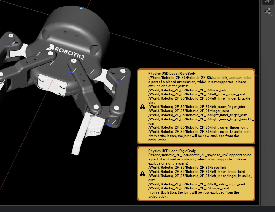
For more information, see Physics Simulation Fundamentals. Articulations must be kinematic trees, but there is no need to delete any joints. To eliminate those warnings, you must choose one joint to exclude from the Articulation and have it be treated as a maximal coordinate joint. Because maximal coordinate joints are treated with a lower priority by the solver, it is the joint that accumulates the most error in simulation.
In terms of simulation efficiency, the best choice of joint to exclude from articulation is the one that minimizes the length of articulations. However, you must also consider utility. The best joint to remove is the one that interferes the least with the robot functionality. In an ideal scenario, the joint to exclude from articulation only serves as a spatial constraint. Identify a joint with no limits, no resistance, and no drive. If there are no joints that meet this criterion, transfer these attributes to the adjacent joints before removing it from articulation.
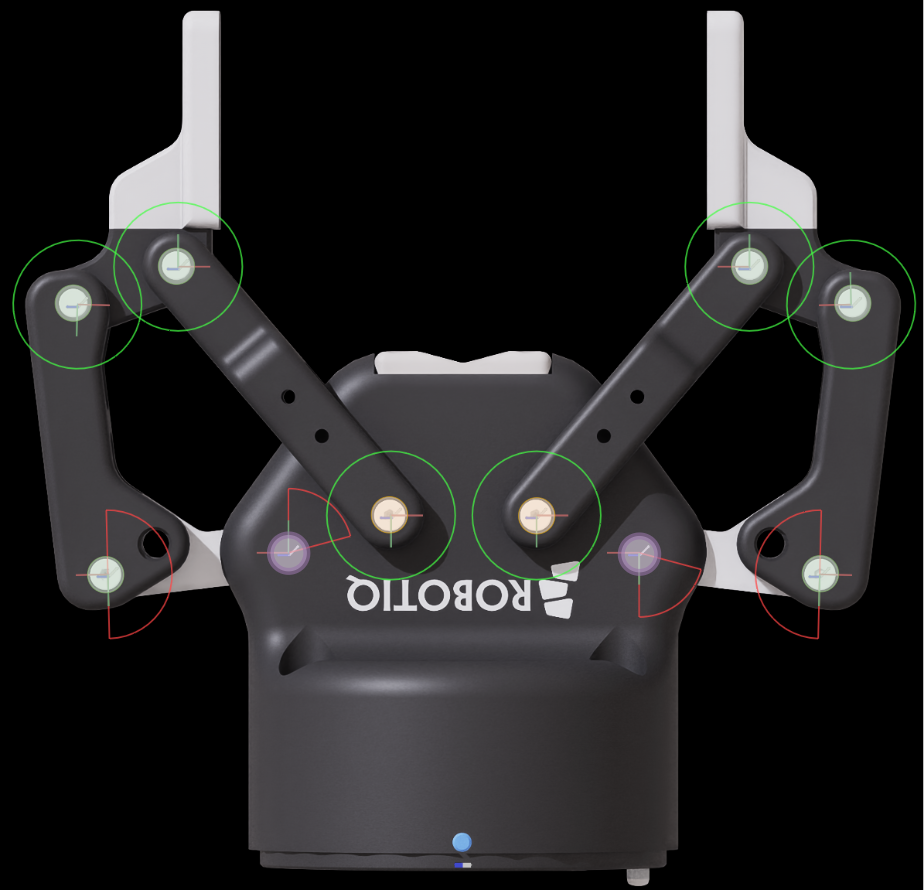
In the case of this gripper, the best options to remove from the articulation are the joints that connect the inner shafts to the gripper body (the inner_knuckle_joint, highlighted in orange in the image).
To remove the joints from the articulation, select the
left_inner_knuckle_jointandright_inner_knuckle_jointprims.In the Joint section under physics, select Exclude From Articulation.
Note
The fully completed asset is located in the Samples/Rigging/Gripper/Robotiq 2F-85_complete folder.
Preparing For Tests#
Because the gripper is not connected to anything to move it and test its physical properties, add a structure to later help us test the stability of the gripper:
Create two Xforms and add the Rigid Body API to them.
Add a fixed joint from world to the first Xform.
Add a Prismatic Joint from the first Xform to the second Xform.
Add a second prismatic joint from the second Xform to
/Robotiq_2F_85/base_link.Add a drive to the prismatic joints so that you can lift and move forward with a position command.
In the drives set the following:
In the Advanced properties for the joint, set a maximum joint velocity of 5.0.
Set the joint limits to [0, 1].
In the joint drive, set the following:
Damping: 10000.0
Stiffness: 10000.0
Make sure to move all joints that were just created outside of the Robotiq_2F_85 prim.
To assist in checking the grip:
Create a Cylinder and scale it to
[0.05, 0.05, 0.2].Place the cylinder at
X=0.12.Set the cylinder collider to
Convex Hull.Create a ground plane and move it to
Z=-0.1.
To assist in creating these prims, use the following script. You can run them by opening a Script Editor (Window > Script Editor) and pasting the code below.
import omni.usd
from pxr import Gf, PhysicsSchemaTools, PhysxSchema, Sdf, Usd, UsdGeom, UsdPhysics

stage = omni.usd.get_context().get_stage()

# Create Xform nodes
xform = UsdGeom.Xform.Define(stage, "/World/Xform")
xform_1 = UsdGeom.Xform.Define(stage, "/World/Xform_1")

# Add Physics Rigid Body API to Xform nodes
for node in [xform, xform_1]:
    UsdPhysics.RigidBodyAPI.Apply(node.GetPrim())
    mass_api = UsdPhysics.MassAPI.Apply(node.GetPrim())
    mass_api.CreateMassAttr(0.1)

# Create Fixed Joint from Xform to Xform_1
fixed_joint = UsdPhysics.FixedJoint.Define(stage, xform.GetPath().AppendChild("fixed_joint"))
fixed_joint.CreateBody1Rel().SetTargets([str(xform.GetPath())])

# Create Prismatic Joints
prismatic_joint_1 = UsdPhysics.PrismaticJoint.Define(stage, "/World/Joint_Z")
prismatic_joint_1.CreateAxisAttr("Z")
prismatic_joint_1.CreateLowerLimitAttr(0.0)
prismatic_joint_1.CreateUpperLimitAttr(1.0)
prismatic_joint_1.CreateBody0Rel().SetTargets([str(xform.GetPath())])
prismatic_joint_1.CreateBody1Rel().SetTargets([str(xform_1.GetPath())])

prismatic_joint_2 = UsdPhysics.PrismaticJoint.Define(stage, "/World/Joint_X")
prismatic_joint_2.CreateAxisAttr("X")
prismatic_joint_2.CreateLowerLimitAttr(0.0)
prismatic_joint_2.CreateUpperLimitAttr(1.0)
prismatic_joint_2.CreateBody0Rel().SetTargets([str(xform_1.GetPath())])
prismatic_joint_2.CreateBody1Rel().SetTargets(
    ["/Robotiq_2F_85/base_link"]
)  # update this to match your robot's base_link prim path
prismatic_joint_2.CreateLocalRot0Attr().Set(Gf.Quatf(1.0))
prismatic_joint_2.CreateLocalRot1Attr().Set(Gf.Quatf(Gf.Rotation(Gf.Vec3d(0, 1, 0), -90).GetQuat()))

# Add Prismatic Joint Drive with damping and stiffness
for joint in [prismatic_joint_1, prismatic_joint_2]:
    drive = UsdPhysics.DriveAPI.Apply(joint.GetPrim(), "linear")
    drive.CreateDampingAttr(8000)
    drive.CreateStiffnessAttr(10000)
    px_joint = PhysxSchema.PhysxJointAPI.Get(stage, str(joint.GetPath()))
    px_joint.CreateMaxJointVelocityAttr().Set(0.5)

# Add Ground Plane
PhysicsSchemaTools.addGroundPlane(stage, "/World/groundPlane", "Z", 100, Gf.Vec3f(0, 0, -0.1), Gf.Vec3f(1.0))

# Create cylinder mesh.
# Use an explicit world-space path and disable prepend_default_prim so the cylinder is NOT
# created under the stage default prim (/Robotiq_2F_85). Nesting it under the robot would make
# its translate inherit the root's 90-degree Y rotation (placing it off to the side instead of
# between the fingertips) and would inject a free rigid body into the articulation hierarchy.
result, path = omni.kit.commands.execute(
    "CreateMeshPrimCommand", prim_type="Cylinder", prim_path="/World/Cylinder", prepend_default_prim=False
)
# Get the prim
cylinder_prim = stage.GetPrimAtPath(path)
cylinder_prim.GetAttribute("xformOp:scale").Set(
    (0.05, 0.05, 0.2)
)  # if your gripper is oriented differently, you may need to update the position and orientation of this cylinder or gripper accordingly to align them.  You can also do this post-creation.
cylinder_prim.GetAttribute("xformOp:translate").Set((0.12, 0, 0))

# Add Rigid Body and Mass API to cylinder
cylinder_body = UsdPhysics.RigidBodyAPI.Apply(cylinder_prim)
UsdPhysics.CollisionAPI.Apply(cylinder_prim)
mesh_collision = UsdPhysics.MeshCollisionAPI.Apply(cylinder_prim)
mesh_collision.CreateApproximationAttr().Set("convexHull")
massAPI = UsdPhysics.MassAPI.Apply(cylinder_body.GetPrim())
massAPI.CreateMassAttr(0.20)

# Create a Physics Scene
scene = UsdPhysics.Scene.Define(stage, Sdf.Path("/physicsScene"))
physxSceneAPI = PhysxSchema.PhysxSceneAPI.Apply(scene.GetPrim())
# This is a Small test scene, no need for GPU Dynamics
physxSceneAPI.CreateEnableGPUDynamicsAttr(False)
Set the target position for Joint X to 1 in the property panel, by going to the Joint Drive section and setting the target position to 1.
Set the target position for Joint Z to 1 in the property panel, by going to the Joint Drive section and setting the target position to 1.
Verify that you see the fingers ragdoll on the screen. It’s still necessary to Tune the Joint Drives for the fingers.
You can see in the video below that the gripper will move forward and lift up.

Until this point, if you start the simulation, you will see the fingers rotate freely, and also you will notice collision clipping between the fingers. This is because the fingers do not have drivers that tell them how to move, and because the finger components are connected with joints, there is a natural collision filter between them. This is normal and expected, and you fix it in the next sections.
Adding Joint Drives#
Add the Joint Drive API to all joints:
Select all joints on the gripper, then, in the Properties panel, Add > Physics > Angular Drive (or Linear Drive for prismatic joints).
In this gripper, the primary drive joint is
finger_joint. Keep its limits at[0, 75]degrees.right_outer_knuckle_jointis coupled through a mimic joint in the next section, not through its own drive.
Select all the joints on the gripper, then, in the Properties panel, Add > Physics > Joint State Angular (or Joint State Linear for prismatic joints).
Model this gripper as a force-driven grasp. For that, position control must be disabled. Select
finger_joint, then set Stiffness to0.17and Damping to0.0002.To control how much pressure is applied when the grippers close, set the
finger_jointMax Force to16.5(Nm).These grippers also have a maximum speed at which they can operate. Converting from the data sheet to angular speed at the fingertips, the angular limit speed is 130 degrees per second.
In the joint section, under the Advanced tab, set the Maximum Joint Velocity to
130.0(deg/s) onfinger_jointandright_outer_knuckle_joint.
For a two-finger grasp, estimate the required normal force at each fingertip as F = m × g / (2 × μ). With a 5 kg payload and μ = 0.8, each fingertip must apply at least 5 × 9.81 / (2 × 0.8) ≈ 31 N. Use 30–45 N as the target range to account for lower effective friction and motion.
Convert the fingertip force to drive torque through the linkage Jacobian, τ = JᵀF. For this gripper near its closed position, the target force range requires approximately 12.75 Nm at finger_joint. Set Max Force to 16.5 Nm to provide approximately 30% torque margin.
The angular drive applies τ = Kp × position_error before the maximum-force limit. The joint travels 75 degrees, so choose Kp = 12.75 Nm / 75 degrees = 0.17 Nm/degree. Enter 0.17 as the USD stiffness. This is equivalent to approximately 9.74 Nm/rad in PhysX units. The 0.0002 damping value suppresses oscillation without materially reducing the closing effort.
Summarizing the finger_joint drive values (USD units):
Maximum Joint Velocity:
130Max Force (Torque):
16.5(Nm)Damping:
0.0002Stiffness:
0.17
When trying to control the fingers now, notice that they instantly bulge inwards instead of moving in parallel. The system still needs stability to maintain the parallel motion when closing without resistance.
The Robotiq hand has a spring mechanism at the outer knuckle to keep the fingers parallel until an object is grasped.
Set the stiffness of
[left, right]_inner_finger_jointto0.0002, damping to0.00001, max force to0.5(Nm), and Target Position to45degrees to achieve this behavior.
Adding Mimic Joint#
This gripper is controlled with a single input command that moves both fingers concurrently. On the right side, right_outer_knuckle_joint follows finger_joint through a mimic joint instead of its own drive.
Select
right_outer_knuckle_joint.If the joint contains a joint drive, in the Properties panel, click Remove Component on the Joint Drive to remove it from this joint entirely. The mimic joint will supply the drive; having a drive API alongside the mimic negatively impacts the outcome.
On the Properties Panel, click on Add > Physics > Mimic Joint.
Note
Because this is a single degree of freedom revolute joint, the schema axis is not relevant. The UI will show rotX as the default axis, despite the joint being defined in the Z axis.
In the Mimic settings, set gearing to
-1.0to make it act in the opposite direction of the reference joint.Set the reference Joint to
finger_joint.Because the closed loop is still partially constrained, configure a compliant mimic on
right_outer_knuckle_jointwith Natural Frequency5000and Damping Ratio0.01.All drive features are copied over from the reference joint, and having an authored joint drive would negatively impact the drive outcome. Compliant mimic parameters use Natural Frequency and Damping Ratio. Do not copy joint-drive stiffness or damping into those fields.
Note
The Rotation Axis for the mimic joint only makes a difference if the joint where mimic is applied contains multiple degrees of freedom (for example, a spherical joint). For prismatic and revolute joints any selection will work just the same. It is still recommended to maintain it aligned with the DOF axis.
Run the simulation again.
Note
The shipped asset at
Isaac/Robots_Multiphysics/Robotiq/2F-85/Robotiq_2F_85.usdastores two physics variants under Physics:
Physx_Loop — the workflow in this tutorial. The kinematic loop is opened by excluding
[left, right]_inner_knuckle_jointfrom the articulation and using a compliant mimic onright_outer_knuckle_joint.Physx_Mimic — the topology used in the Omni Physics Joint Parameter Tuning Example: 2F-85. The loop is removed by fixing the outer-finger joints, and five hard mimic joints follow a single drive on
finger_joint.
For gain derivation from robot specifications, use the Omni Physics guide and Tutorial 11: Tuning Joint Drive Gains. For loop breaking and layered authoring, continue with this tutorial and the Physx_Loop variant values above.
The fully completed asset is located in the Samples/Rigging/Gripper/Robotiq 2F-85_complete folder. For gain derivation from robot specifications, see Tutorial 11: Tuning Joint Drive Gains.
Collision Meshes#
The default setting for collision meshes at import is Convex Hull. This is a good balance between performance and accuracy. However, for grippers, you often want the fingertips to have a collision mesh that closely follows the contour of the fingertip geometry, so that there won’t be any gaps between the fingertips and the objects being grasped.
To visualize the collision meshes:
Find the eye icon on top of the viewport, and click Show By Type > Physics > Colliders > All.
Verify that outlines show up surrounding any objects that have collision meshes.
Optionally, to change any collision meshes, select the part of the object associated with that mesh by clicking on it in the viewport, and then in the Physics section of the Property panel, change the Collider Approximation type to Convex Decomposition, or any other type that’s appropriate for your use case.
If you don’t see a Physics or Collider section, then you might need to go down or up the stage tree from the selected item.
The collision API can be applied to a nested child Xform, or the parent of the selected object.
Self-Collision#
During your tests you may notice that the fingers are not colliding against each other. Self-collision is disabled by default. To enable it:
Select
/Robotiq_2F_85.Check Self-Collision Enabled in the Articulation Root Options.
Note
For more details on how to tune the articulation, refer to Joint Parameter Tuning Example: 2F-85.
Saving Results#
After you are satisfied with the configuration, save the authoring layer:
Open the Layer tab.
Ensure
Robotiq_2F_85_edit.usdcis the active authoring layer.Click the Save Layer button on
Robotiq_2F_85_edit.usdc.
Note
The fully completed asset is located in the Samples/Rigging/Gripper/Robotiq 2F-85_complete folder.
Test the Gripper#

Now we can test the gripping by lifting the gripper and moving it forward, while closing the gripper to grasp the cylinder.
- Set the target position for
Joint X to 0.1 in the property panel, by going to the Joint Drive section and setting the target position to 0.1.
Joint Z to 0.1 in the property panel, by going to the Joint Drive section and setting the target position to 0.1.
Finger joints to
+40degrees in the property panel, by going to the Joint Drive section and setting the target position to40.
You can see in the video below that the gripper will move forward and lift up.
Note
The fully completed asset is located in the Samples/Rigging/Gripper/Robotiq 2F-85_complete folder.
Summary#
In this tutorial, you worked from a pre-built gripper base asset, applied physics drives and a mimic joint to control parallel finger motion, broke a closed articulation loop using exclude-from-articulation, and configured effort drives with correct gain values. You conducted validation and troubleshooting to address simulation behavior issues, and optimized performance. Additionally, you utilized layered editing to prepare a ready-to-use asset while retaining a test environment for validating gripper functionality.