


Tutorial 11: Tuning Joint Drive Gains#
Learning Objectives#
In this tutorial, you use the Gain Tuner to bring an un-tuned UR10 manipulator from zero gains to a working set of stiffness and damping values. Along the way you learn how to:
Diagnose missing or insufficient gains with the Snap to Limits test.
Distinguish Fail from Blocked results using the Disable Self-Collisions toggle.
Validate tuned gains with the Stress test and observe how velocity limits contribute to solver stability.
For a full explanation of how the Gain Tuner works, the physics behind joint drives, and the complete parameter reference for each test, see Gain Tuner Extension.
10-15 Minute Tutorial
Prerequisites#
Complete the Tutorial: Import URDF tutorial to import the UR10 onto the stage. The URDF importer sets all joint stiffness and damping to zero by default, so the robot has no active drives.
Read the Gain Tuner Extension reference for background on the parameters, physics, and detailed result interpretation guide.
Important
This tutorial and its screenshots assume the default PhysX backend (./isaac-sim.sh or isaac-sim.bat), where both the Position and Effort charts appear after a test. If you launch with the Newton backend (./isaac-sim.newton.sh or isaac-sim.newton.bat), only the Position charts and the results tables appear — the Effort chart is omitted. That is expected: Newton does not currently report measured joint forces. Position-chart and Pass/Fail/Blocked results are unaffected. See Visualizing Results.
Step 1: Open the Gain Tuner and observe zero gains#
Go to Tools > Robotics > Asset Editors > Gain Tuner.
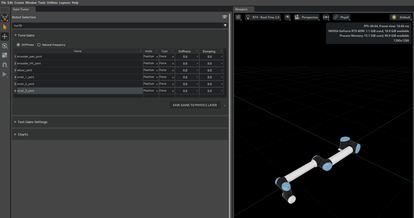
Select the UR10 from the Robot dropdown in the window header. The Gain Settings tab shows every tunable joint as one row in the table.
Observe that all six joints —
shoulder_pan_joint,shoulder_lift_joint,elbow_joint,wrist_1_joint,wrist_2_joint,wrist_3_joint— have Stiffness and Damping set to0. With zero gains the robot has no active drives and will collapse under gravity when the simulation is played.
Step 2: Snap to Limits with weak gains#
Set initial gains to see how the robot responds with deliberately low stiffness and no damping:
On the Gain Settings tab, select all six joints (click the first row, then Shift-click the last), then type
10into the Stiffness cell of any selected row. The value is applied to every selected joint at once. Leave Damping at0.Switch to the Test Gains tab. In the per-joint test-configuration table, enable the Test checkbox for all joints.
Select the Snap to Limits test mode (the default) in the Test Mode selector.
Press Run Test. The Gain Tuner starts the timeline for you if the simulation is not already playing.
After the test finishes, inspect the results table and the trajectory charts below it. On PhysX you see Position and Effort charts; on Newton you see Position charts only (see the Prerequisites note above).
With stiffness at only 10 Nm/rad and no damping, expect:
shoulder_lift_jointandelbow_jointare likely to Fail. These joints bear the full weight of the arm and 10 Nm/rad of stiffness is far too low to drive them to their limits.Wrist joints may also Fail or show long settling times with oscillation, since there is no damping to absorb overshoot.
Some joints may report Blocked if the collision geometry prevents them from reaching a limit.

Note
With damping at 0 the joints oscillate instead of settling, so every approach phase runs to its 10-second timeout and the test takes several times longer than the progress bar’s estimate. Once the run passes its estimate the bar holds just short of full and the readout switches to reporting elapsed time against the estimate, for example Time: 45.0s (est. 27.0s). Let the run finish — stopping it early discards the recorded data, and no charts are produced.
Note
If a joint reports Blocked, re-run with Disable Self-Collisions enabled. If the joint then passes, the joint limit extends beyond what the collision geometry allows — tighten the joint limit in USD rather than adjusting gains.
Step 3: Tuned parameters#
Before adjusting gains, check the joint force limits. The UR10’s URDF defines max effort values (330 Nm for the shoulder joints, 150 Nm for the elbow, 56 Nm for the wrist joints) that are imported as the joint Max Force in USD. With high stiffness, the PD controller may need to apply forces that exceed these limits to drive the heavy shoulder and elbow links to their targets. If a joint still fails Snap to Limits after increasing stiffness, raise its max force to a higher value or to not limited (infinite, set by clicking the blue box next to the value to remove the limit) — either as Max Drive Force in the Gain Tuner detail panel’s Advanced Actuator Parameters section, or in the Properties panel under Joint > Advanced > Maximum Force. For the UR10, shoulder_pan_joint and shoulder_lift_joint require infinite max force to pass.
The following gains produce a UR10 that passes Snap to Limits. They were found using the position-drive tuning heuristic described in the Tuning Workflow section of the Gain Tuner reference:
Joint |
Stiffness |
Damping |
|---|---|---|
|
500000 |
50 |
|
500000 |
50 |
|
50000 |
50 |
|
500 |
0.5 |
|
500 |
0.5 |
|
50 |
0.0 |
Note
These values are starting-point examples. Fine-tune them for your specific application by iterating with the Gain Tuner tests. The shoulder and elbow joints require higher gains because they bear the weight of the full arm, while the lighter wrist joints respond well at lower values.
Enter these values in the Stiffness and Damping columns, re-run the Snap to Limits test, and confirm that all joints now Pass.
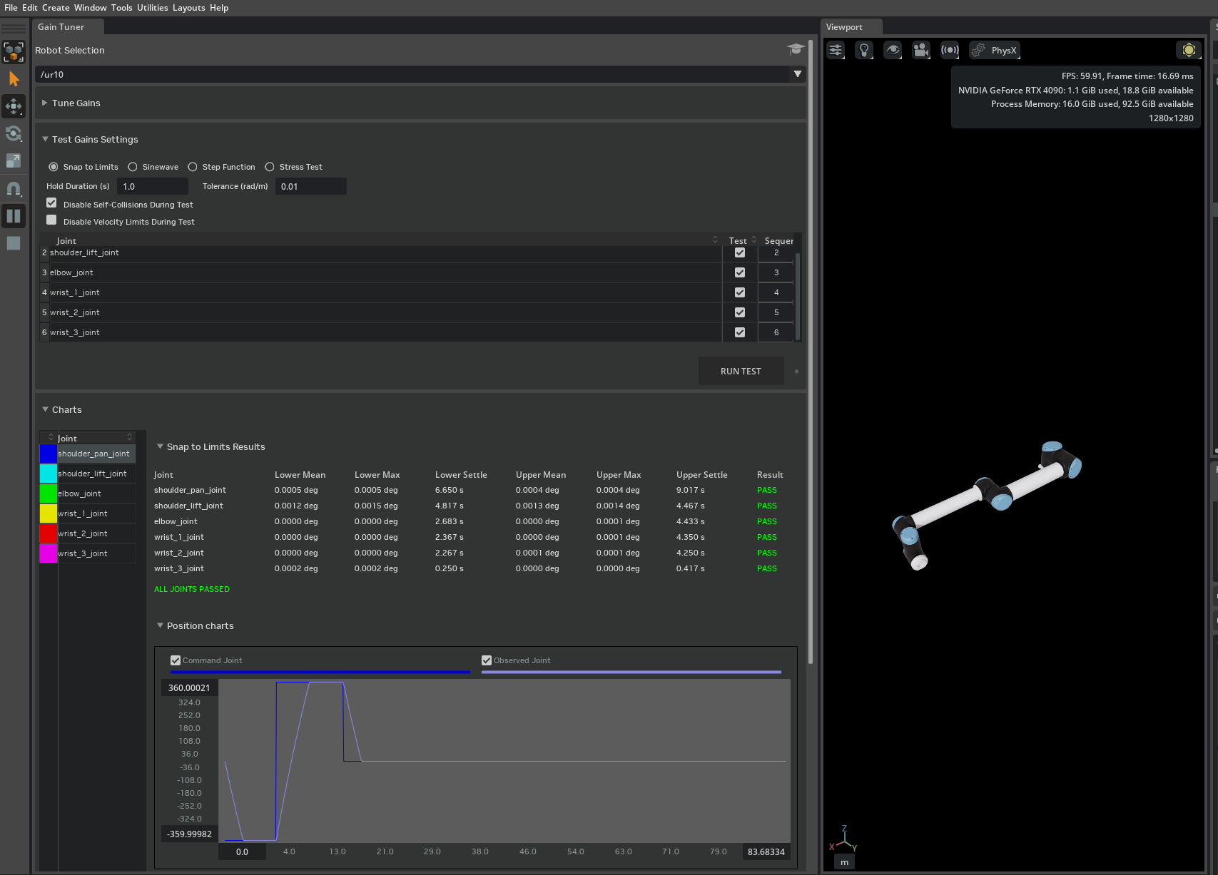
You can further validate tracking quality with the Sinusoidal and Step Function test modes. For configuration details and result interpretation, see Sinusoidal and Step Function.
Step 4: Stress test with tuned gains#
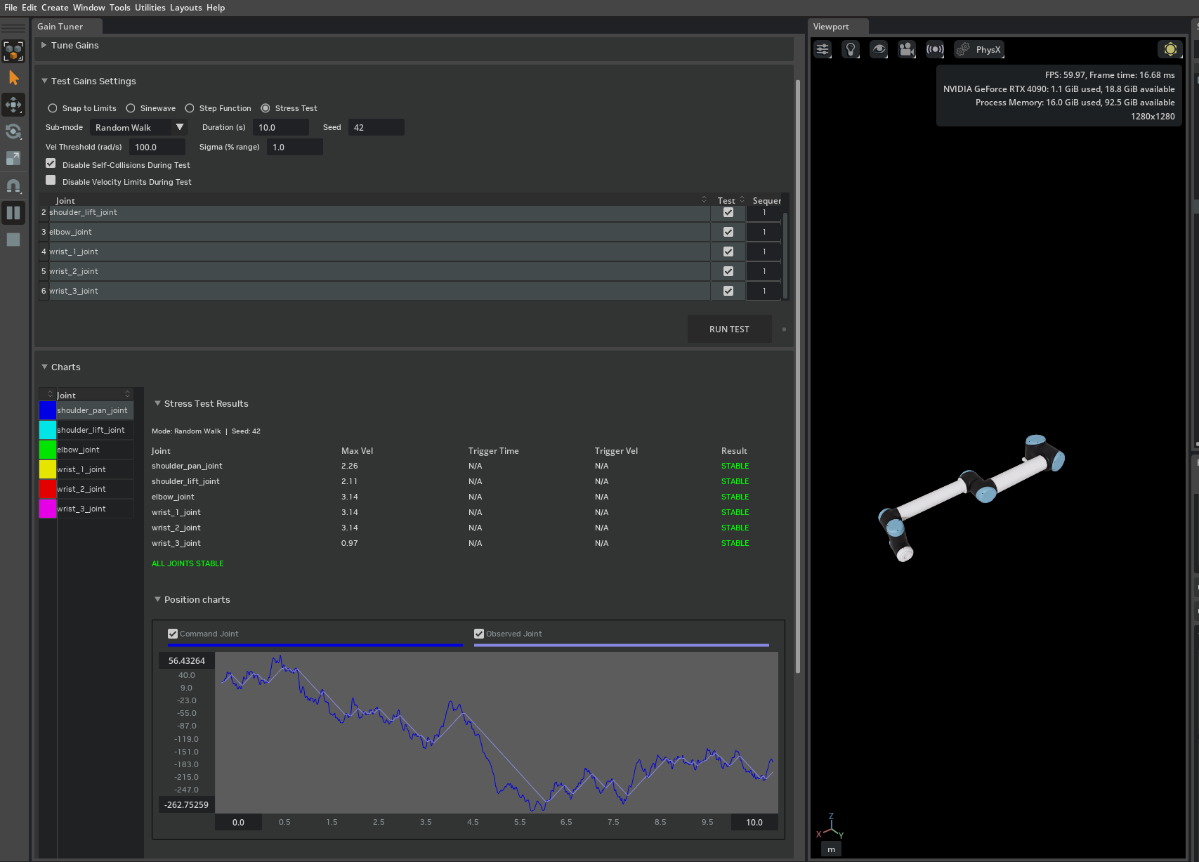
With the tuned gains from Step 3: Tuned parameters applied, run the Stress test to verify the robot is stable under the extreme commands typical of reinforcement learning training:
On the Test Gains tab, select the Stress test mode and choose the Random Walk sub-mode.
Set Sequence for all joints to
1so that the joints are tested in parallel.Leave Disable Velocity Limits off (the default).
Press Run Test.
All joints should report Stable.
Now observe what happens without velocity limits:
Enable Disable Velocity Limits.
Press Run Test again.
Some joints now report Unstable.
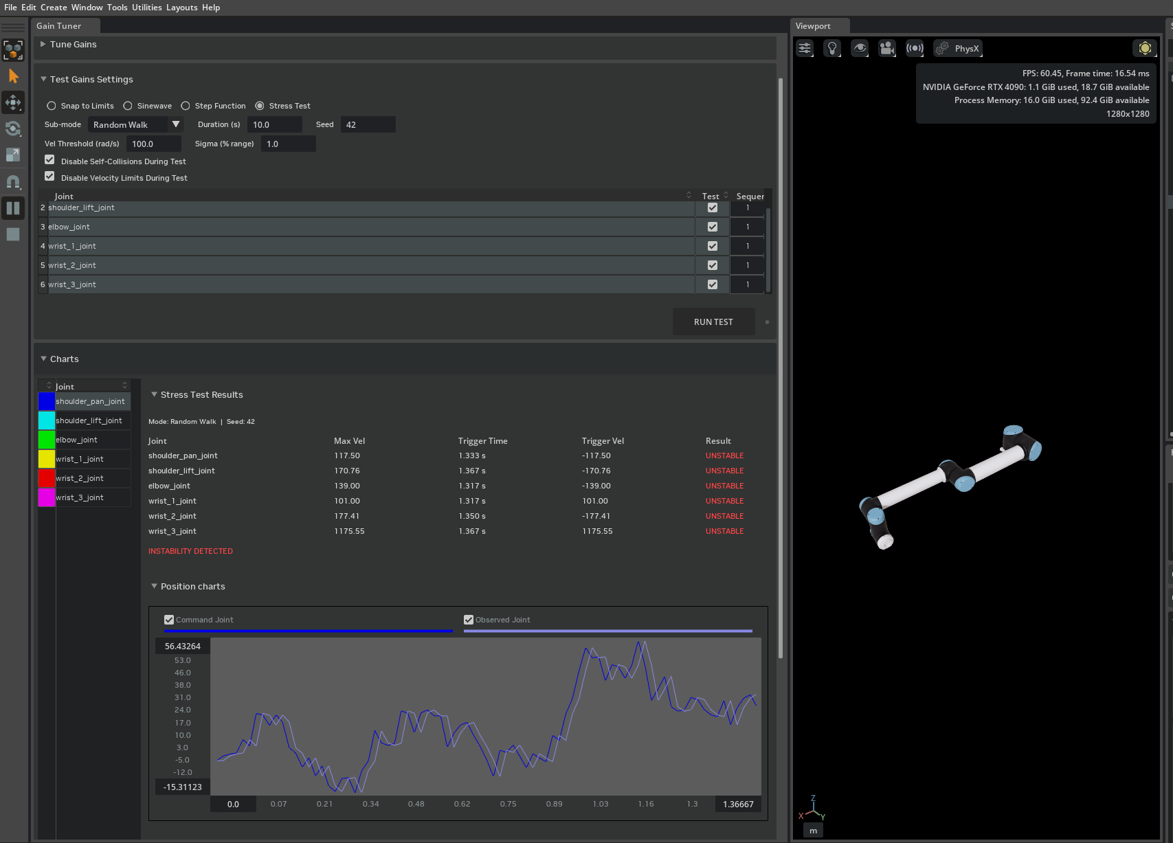
Without velocity limits, the PD controller responds to the stress test’s large position errors by generating forces that accelerate joints to extreme speeds within a single simulation timestep. At these speeds the discrete-time solver can fail to converge, leading to energy blowup or NaN values.
Velocity limits serve two purposes:
Physical fidelity — real actuators have maximum speeds defined by the manufacturer. The UR10’s URDF specifies velocity limits of approximately 2–3 rad/s per joint. Setting these in simulation reproduces the real robot’s motion envelope.
Solver stability — by capping joint speed, velocity limits keep per-step displacements within the range where the PhysX implicit integrator remains numerically stable.
If your application requires higher velocity limits than the manufacturer specification, increase them incrementally and re-run the Stress test after each change to confirm the solver remains stable at the new limits.
Repeat the comparison in Adversarial sub-mode to confirm the same behavior under worst-case correlated configurations.
Note
A Stable result is meaningful only at the sigma and snap interval values used. When assessing readiness for Isaac Lab training, record these parameters alongside results. See Stress for a full explanation of how to interpret each result combination.
Tuning under the Newton backend#
UsdPhysics.DriveAPI is backend-agnostic: the drive actuates the joint under Newton exactly as it does under PhysX, and Newton converts revolute gains from the per-degree convention USD authors them in to the per-radian convention it solves in, so you never rescale them by hand.
Important
Enter DriveAPI stiffness and damping in the same per-degree convention under either backend. Switching the active backend to Newton relabels the Stiffness and Damping fields rad, but the value stored in USD is unchanged and is still interpreted per degree. Rescaling a gain by 180/π to match that label leaves the joint roughly 57 times too stiff for PhysX once you switch back.
What does not carry over is the tuned values themselves. The stiffness and damping in Step 3: Tuned parameters were found against PhysX. Applied unchanged under Newton with the MuJoCo solver, they fail Snap to Limits on every UR10 joint, and the shoulder_pan, shoulder_lift, and elbow joints diverge outright instead of settling. Treat Newton as a separate tuning exercise: follow the same workflow as the steps above, but re-tune from scratch against Newton rather than carrying the PhysX table over.
Which source actually drives a joint depends on what the asset authors, not on the active backend:
A Newton actuator on the joint takes precedence under either backend.
Otherwise MuJoCo-native (
mjc:*) actuator gains take over when the asset authors them and the live Newton solver is the MuJoCo solver.Otherwise the DriveAPI drive actuates the joint, on Newton as on PhysX.
The Gain Tuner reports the winning source in the Source column and makes only that source editable, so the column tells you which gains a test will actually exercise. A UR10 imported from URDF as a PhysX-only asset has no MuJoCo source to select, so its DriveAPI gains are the ones Newton actuates — which is why they still have to be tuned for Newton. See Physics Backends and Gain Sources.
Two things are worth checking when a robot is stable on PhysX but not on Newton:
Gains authored on both sources. Do not leave non-zero DriveAPI stiffness or damping on a joint that also has a MuJoCo actuator. Both apply force independently under Newton and the combined result is undefined. See Common pitfalls.
Missing armature. Armature reflects rotor inertia at the joint, and omitting it is a common source of solver instability on high-gear-ratio joints. It is authored per backend: the Gain Tuner’s Armature field writes
newton:armatureunder Newton andphysxJoint:armatureunder PhysX, so tuning it on one backend leaves the other untouched. Use Copy To PhysX or Copy To Newton to seed the backend that has nothing authored.mjc:armatureis read only under the Newton MuJoCo solver, and only whennewton:armatureis unauthored. See Advanced actuator parameters and Tips.
Identical gains do not produce an identical response, because armature, contact handling, substepping, and the default solver rate all differ between the backends. Always re-run Snap to Limits under Newton and tune against its results: a robot that passes on PhysX can be violently unstable on Newton at the same gains.
If you instead author MuJoCo gains directly, derive them with the mapping table in Quick guide: manually mapping DriveAPI gains to MuJoCo attributes — that path is hand-authored, so units and sign conventions differ and no automatic conversion applies — then save with the MuJoCo target selected so the values land in mujoco.usda. See Save Targets and Backend Mirroring.
Summary#
This tutorial covered:
Starting from an un-tuned UR10 imported from URDF with zero gains.
Using Snap to Limits to identify joints with insufficient stiffness and distinguishing Fail from Blocked results.
Applying tuned gains and confirming all joints pass Snap to Limits.
Using the Stress test to demonstrate why velocity limits are important for solver stability.
Note
Reminder: on the Newton backend the Effort chart is omitted. See the Prerequisites note and Visualizing Results.