


Generating an XRDF file#
This tutorial is for users who need to configure a custom robot that is not
available through load_cumotion_supported_robot(). It shows how to use
the Robot Description Editor to generate an
XRDF
file for use with cuMotion. The editor lets you define joint properties and
collision-sphere geometry directly from a robot USD asset on the stage, then
export the result as an XRDF file.
Prerequisites#
Enable the cuMotion/Lula Robot Description Editor extension: go to Window > Extensions, search for
isaacsim.robot_setup.xrdf_editor, click ENABLE, and check AUTOLOAD.A robot USD asset loaded on the stage as a single Articulation. Open the file by dragging it onto an empty stage rather than opening it directly.
Note
The Robot Description Editor is not compatible with Instanceable Assets. An XRDF file generated for a non-instanceable asset will still work on an instanceable version of that asset.
To use the editor, uncheck the Instanceable checkbox for all geometry
prims in the robot hierarchy. Find this setting in the Property panel
when a geometry prim is selected.
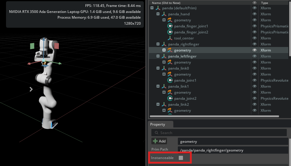
Uncheck the Instanceable checkbox (highlighted in red) for all geometry
prims before using the Robot Description Editor.#
Getting started#
Open the Robot Description Editor from the menu bar: Tools > Robotics > cuMotion/Lula Robot Description Editor.
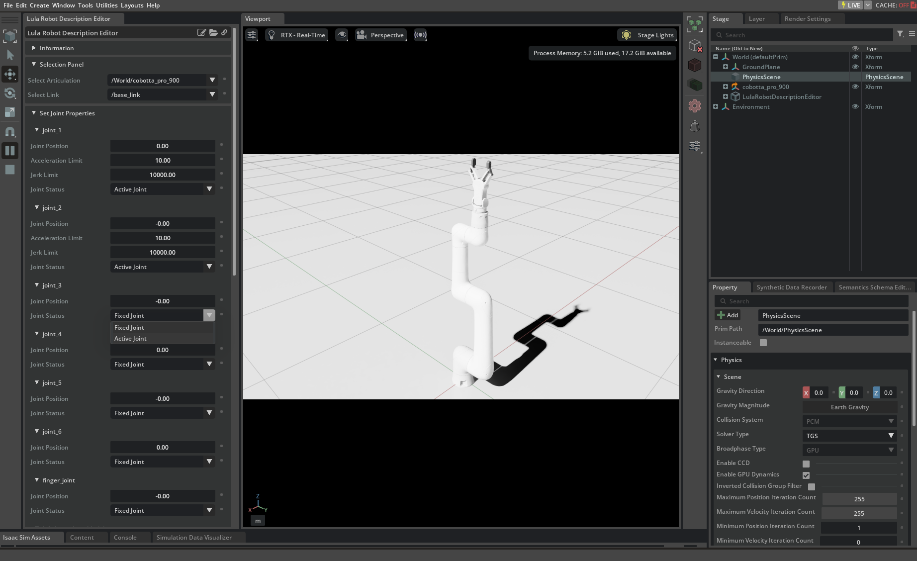
Click the Play button. In the Selection Panel, select the prim path of your robot Articulation from the Select Articulation field. After the articulation is selected, the Select Link drop-down populates with the robot’s link names and all other panels fill with robot-specific data.
Important
Keep the simulation running until you have exported the XRDF file.
Set joint properties#
In the Set Joint Properties panel, assign a Joint Position and a Joint Status to each joint:
Active joints are directly controlled by cuMotion — typically each joint in the robot arm. At least one joint must be marked as active.
Fixed joints are held at a constant default position — typically the gripper joints. The fixed-joint positions define the robot’s default configuration and influence null-space behavior during reactive control.
Adding collision spheres#
cuMotion uses a set of spheres attached to each robot link for collision avoidance. Add spheres one link at a time by selecting a link from the Select Link field.
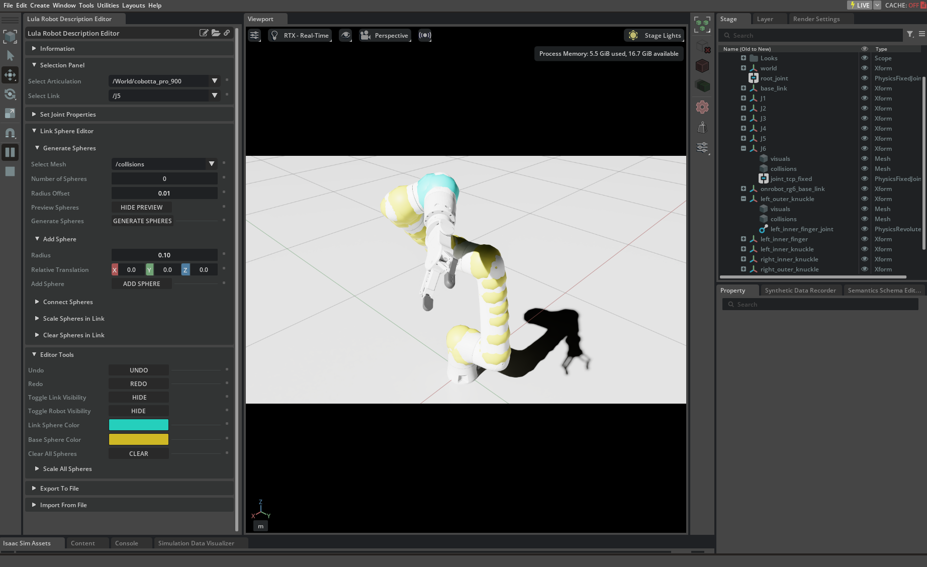
The Link Sphere Editor panel offers three methods:
Add Sphere: Add a single sphere at a specified translation relative to the link origin. Adjust it after creation by moving the prim on the stage or editing its radius.
Connect Spheres: Select two existing spheres under a link and fill the gap with a specified number of interpolated spheres, sized to cover the cone section between them.
Generate Spheres: Select a mesh defining the link volume and automatically generate N spheres to cover it. A preview appears before you confirm with Generate Spheres. This method requires a watertight triangle mesh. For links with simple cylindrical shapes, Connect Spheres typically gives better coverage.
The Editor Tools panel provides Undo / Redo, sphere color controls, and a robot-visibility toggle.
Sphere tuning tips
Size spheres to cover the link without being oversized — large spheres increase solver conservatism and can degrade motion quality.
More spheres improves collision accuracy but reduces solver performance. Find the minimum count that gives adequate coverage.
For long cylindrical links, generate spheres on each end and use Connect Spheres to fill the middle evenly.
Use Scale Spheres in Link to resize all spheres on a link uniformly.
Generate Spheres requires a watertight triangle mesh. If it fails for a link, place spheres manually using Add Sphere and Connect Spheres.
Exporting an XRDF file#
After completing joint properties and collision spheres, export the XRDF file:
Export To File > Export to cuMotion XRDF. Use .xrdf as the file
extension (.yaml is also accepted if you are using Lula, the legacy
precursor to cuMotion). The Export button becomes available once you
enter a valid path.
A version drop-down lets you choose XRDF format version 1.0 or 2.0 (version
2.0 is recommended; version 1.0 uses collision, version 2.0 uses
world_collision). When exporting, the editor:
Creates a single collision group used for both
world_collision(orcollisionin version 1.0) andself_collision, populated with the spheres you defined.Sets each link in
self_collisionto ignore its parent link and any sibling links that share the same parent.Does not write Tool Frames.
Does not write Modifiers.
You can stop the simulation after the file is saved.
Merging with an existing XRDF file#
If the file path points to an existing XRDF file, an option to Merge With Existing XRDF appears. When merging, the editor:
Copies Tool Frames from the existing file.
Copies Modifiers from the existing file.
Copies
self_collision > ignoreentries from the existing file when theself_collision > geometrymatches the exported collision group geometry.Copies collision spheres from the existing file for any links not represented in the editor.
Adding a tool frame#
cuMotion requires a tool frame in the XRDF file to define the end-effector reference for motion planning. The Robot Description Editor does not write tool frames, so you must add one manually after exporting.
Open the exported XRDF file in a text editor and add a tool_frames entry,
substituting the name of your robot’s end-effector link:
tool_frames: ["wrist_3_link"]
If you are using the Merge With Existing XRDF option, tool frames from the existing file are preserved automatically — see Merging with an existing XRDF file above.
Importing an XRDF file#
To load an existing XRDF file into the editor: Import From File > Import XRDF
File. Both format version 1.0 and 2.0 are supported. The editor imports
collision spheres and joint properties; Modifiers, Tool Frames, and
self_collision entries are not imported. Importing overwrites all current
editor state.
Summary#
This tutorial covered:
Extension setup: Enabling the Robot Description Editor and preparing the robot asset
Joint properties: Classifying joints as active or fixed and setting default positions
Collision spheres: Adding per-link spheres using Add Sphere, Connect Spheres, and Generate Spheres
XRDF export: Exporting the XRDF file, choosing a format version, and optionally merging with an existing file
Tool frame: Manually adding a tool frame to the exported XRDF
XRDF import: Loading an existing XRDF file back into the editor
The XRDF file produced here is the required input for all cuMotion motion planning and control components.
Next steps#
World Interface tutorial - Setting up world state for motion planning
RMPflow tutorial - Reactive, obstacle-aware motion control
Graph Planner tutorial - Sampling-based path planning
Trajectory Generator tutorial - Trajectory-based motion
Trajectory Optimizer tutorial - Optimization-based trajectory planning
cuMotion library documentation - Advanced XRDF and kinematics configuration