ROS 2 Putting It All Together#
Learning Objectives#
In this example, you will use ideas introduced in many other ROS 2 and Isaac Sim tutorials to go from a robot URDF definition to a fully ROS 2-driven robot system.
Import a URDF robot model into Isaac Sim
Incorporate physics and collision properties into the robot model
Attach physically accurate sensors to the model
Build out publisher and subscribers using code or OmniGraph to connect the robot to the ROS 2 network
Integrate a navigation stack to enable the robot to move around an environment
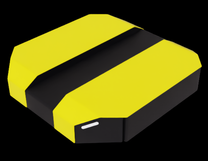
This tutorial uses the Clearpath Robotics Dingo-D as the robot model. It is a differential drive robot made for indoor use.
Getting Started#
Prerequisites
Completed ROS 2 Installation (Default) so that ROS 2 is available, the ROS 2 extension is enabled, and necessary environment variables are set.
Enable the
isaacsim.ros2.bridgeExtension in the Extension Manager window by navigating to Window > Extensions.Have cloned the IsaacSim-ros_workspaces repo and sourced the workspace.
Warning
This tutorial supports the PhysX SDK backend only; Newton is not supported because these assets use negatively scaled meshes. See Newton asset compatibility.
Importing the URDF#
Use the URDF Importer Extension to import the robot into Isaac Sim. This involves first generating a URDF, and then publishing it to the /robot_description topic.
Generate the Robot Description#
In a ROS-sourced terminal, install the Clearpath Robotics packages and other necessary dependencies.
sudo apt install ros-$ROS_DISTRO-clearpath-common ros-$ROS_DISTRO-xacro
All Windows commands in this tutorial use PowerShell syntax. Run them from a PowerShell terminal with the ROS 2 workspace sourced.
These packages are included with your sourced ROS 2 workspace; no additional install step is required.
Set a convenience variable pointing to the
isaacsim_clearpath_nav2package’s params directory. All generated files will be stored here. Any Clearpath robot configuration will work; this tutorial uses the Dingo-D (dd100).export ROBOT_PARAMS=$(ros2 pkg prefix isaacsim_clearpath_nav2)/share/isaacsim_clearpath_nav2/params/dd100
$env:ROBOT_PARAMS = "$(ros2 pkg prefix isaacsim_clearpath_nav2)\share\isaacsim_clearpath_nav2\params\dd100"
Copy the sample Dingo-D configuration as
robot.yaml.cp $(ros2 pkg prefix clearpath_config)/share/clearpath_config/sample/dd100_default.yaml $ROBOT_PARAMS/robot.yaml
Copy-Item "$(ros2 pkg prefix clearpath_config)\share\clearpath_config\sample\dd100_default.yaml" `
          "$env:ROBOT_PARAMS\robot.yaml"
Generate the robot description with the Clearpath generator.
ros2 run clearpath_generator_common generate_description -s $ROBOT_PARAMS
python "$(ros2 pkg prefix clearpath_generator_common)\lib\clearpath_generator_common\generate_description" -s $env:ROBOT_PARAMS
Launch the robot description node to publish the URDF on the
/robot_descriptiontopic. Keep this terminal open.ros2 launch clearpath_platform_description description.launch.py -- setup_path:=$ROBOT_PARAMS
ros2 launch clearpath_platform_description description.launch.py -- setup_path:=$env:ROBOT_PARAMS
Full copy-paste command
export ROBOT_PARAMS=$(ros2 pkg prefix isaacsim_clearpath_nav2)/share/isaacsim_clearpath_nav2/params/dd100
cp /opt/ros/$ROS_DISTRO/share/clearpath_config/sample/dd100_default.yaml $ROBOT_PARAMS/robot.yaml
ros2 run clearpath_generator_common generate_description -s $ROBOT_PARAMS
ros2 launch clearpath_platform_description description.launch.py -- setup_path:=$ROBOT_PARAMS
$env:ROBOT_PARAMS = "$(ros2 pkg prefix isaacsim_clearpath_nav2)\share\isaacsim_clearpath_nav2\params\dd100"
Copy-Item "$(ros2 pkg prefix clearpath_config)\share\clearpath_config\sample\dd100_default.yaml" `
          "$env:ROBOT_PARAMS\robot.yaml"
python "$(ros2 pkg prefix clearpath_generator_common)\lib\clearpath_generator_common\generate_description" -s $env:ROBOT_PARAMS
ros2 launch clearpath_platform_description description.launch.py -- setup_path:=$env:ROBOT_PARAMS
Import into Isaac Sim#
Use the URDF Importer Extension to import the robot description directly from the running robot description node you created in the previous step.
Launch Isaac Sim from a terminal where an IsaacSim-ros_workspaces build is sourced.
Install and enable the
isaacsim.ros2.urdfextension in the Extension Manager window by navigating to Window > Extensions.Navigate to File > Import from ROS2 URDF Node.
Type
robot_state_publisherin the ROS 2 Node text box and click Find Node. It should say “ROS package paths resolved” if it was successful.Click Import to import the robot description.
Rename the default prim to
dd100.Save the stage with
SHIFT+CTRL+Sasdd100.usd.
Adjust Model Physics#
By default, the imported URDF model has a few oddities to fix.
Disable non-physical joints. The URDF, and USD as a result, has some unnecessary joints. Disable all joints except
front_left_wheel_joint,front_right_wheel_joint, andrear_caster_jointjoints. This can be done by clicking each joint with CTRL+LMB in the Stage Tree and deselecting Joint Enabled under Physics.Update the Damping of the
front_left_wheel_jointandfront_right_wheel_jointto10000. This enables velocity control of the robot. You can find Damping under Physics > Drive in the Property tab of each joint.Add more accurate friction coefficients. The robot is a differential drive bot, so the rear caster should slide freely while the drive wheels need good traction.
Create two physics materials under
/dd100/Materials:CasterMaterialwith Dynamic Friction and Static Friction set to0.0, andWheelMaterialwith both set to1.0. You can create a new material by clicking Create > Physics > Physics Material and selecting Rigid Body Material.Assign
CasterMaterialtorear_casterandWheelMaterialtofront_left_wheel_linkandfront_right_wheel_link. You can find these prims using the search bar, then apply the material via the Materials on selected models dropdown.
Create an empty Xform by clicking Create > Xform, move it to
/dd100/Geometry/base_link/chassis_link, and call itbase_link. This will be used in ROS to represent the robot’s base transform.
Ensure you save the stage.
Test the URDF in Isaac Sim#
To verify the import, construct a simple environment and add the robot to it.
Create a new stage with
CTRL+N.Add an existing environment at Create > Environments > Flat Grid.
In the Content browser, drag the USD file you created in the previous step onto the stage.
Zero out the Translate components in Transform to place the robot at the origin. Click Add Transforms if no Transform is present.
As a quick test, for both wheel joints, set the Target Velocity to 100. You can find Target Velocity under Physics > Drive in the Property tab of the front_left_wheel_joint and front_right_wheel_joint joints.
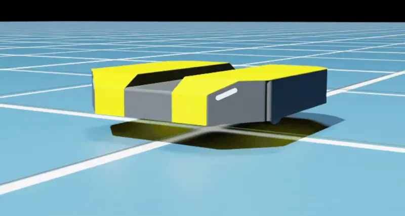
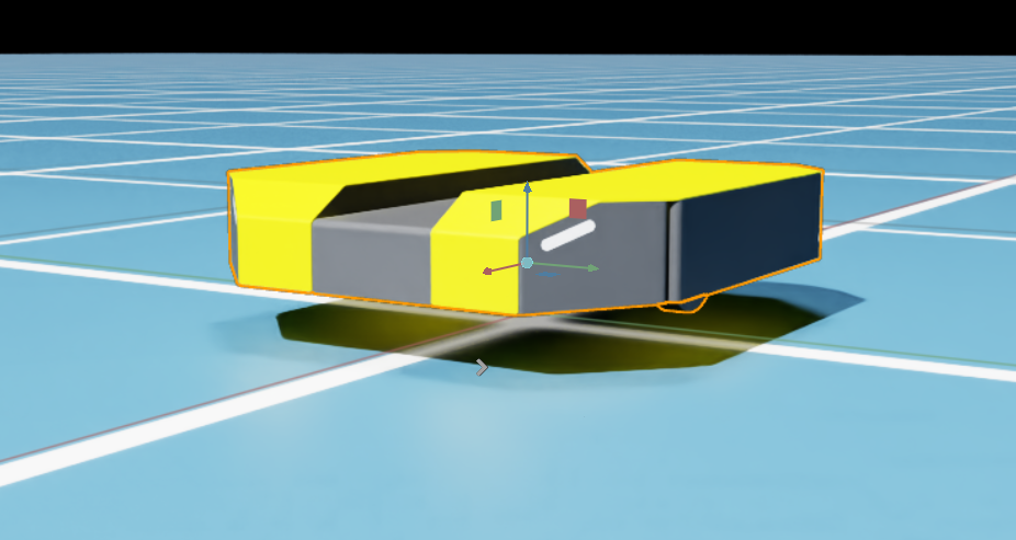
Dingo-D moving forward after wheel joint Target Velocity is applied.#
Adding Sensors#
To allow the robot to perceive the environment, create a few sensors.
Open the robot USD you created earlier using File > Open or by double-clicking it in the Content browser.
Save the stage as
dd100_with_sensors.usd.Start by adding a common off-the-shelf camera, the RealSense D455.
Create the sensor by clicking Create > Sensors > Camera and Depth Sensors > RealSense > Realsense D455.
Drag the sensor to
/dd100/Geometry/base_link/chassis_linkand rename it tosim_camera.Set Translate components to
(0.3, 0, 0.05)to position it at the front of the chassis.By default, the RealSense is a Rigid Body affected by gravity. To fix it to the robot, click
/dd100/Geometry/base_link/chassis_link/sim_camera/RSD455and uncheck Rigid Body Enabled under Physics in the Property tab.
Next add a LiDAR.
Create the sensor by clicking Create > Sensors > RTX Lidar > SICK > microScan3.
Drag the sensor to
/dd100/Geometry/base_link/chassis_linkand rename it tosim_lidar.Set Translate components to
(0.0, 0.0, 0.15)to position it above the chassis.
Save the stage.
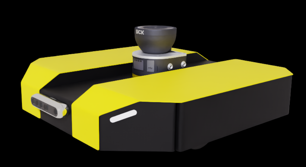
DD100 with sensors attached: a RealSense D455 depth camera on the front and a SICK LiDAR on top.#
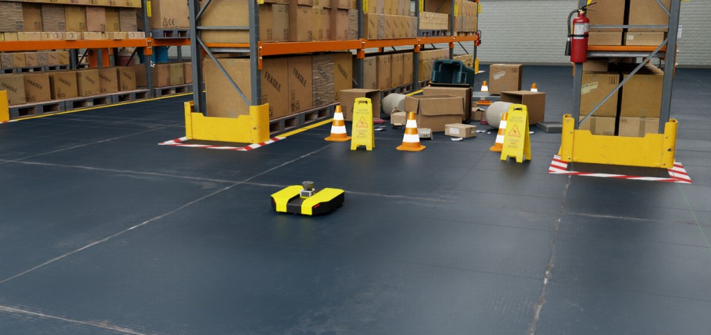
Next, place the robot in a visually interesting environment.
Create a new stage with
CTRL+N.Drag in a warehouse environment from the Content browser at Isaac Sim > Environments > Simple_Warehouse > warehouse.usd.
Zero out the Translate components.
Drag the
dd100_with_sensors.usdUSD file onto the stage.Set the Translate components to
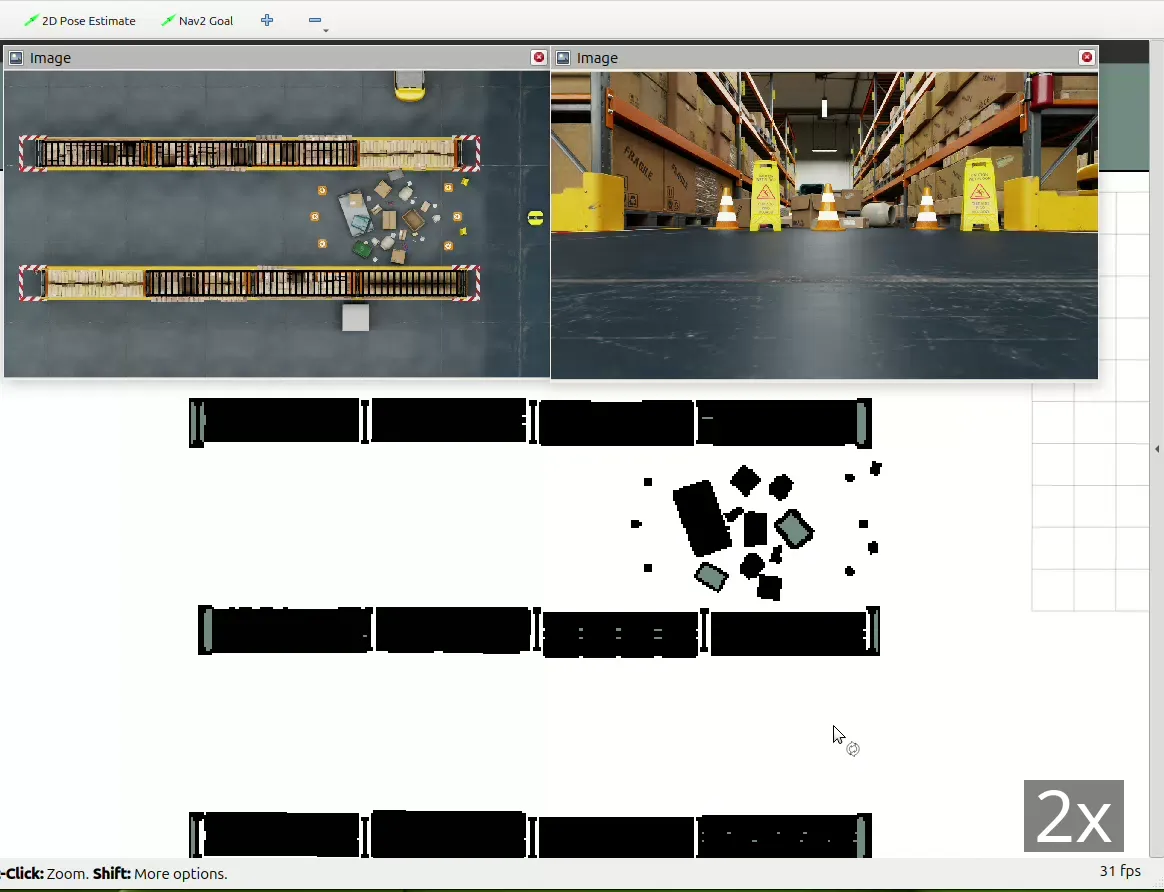
(-5.0, 10.0, 0.0)and the Orient components to(0.0, 0.0, 135.0).To see what the robot sees, create an additional viewport by clicking Window > Viewports > Viewport 2.
In the second viewport, change the camera by clicking Perspective at the top left and selecting Cameras > Camera_OmniVision_OV9782_Color.
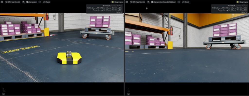
DD100 in the Simple Warehouse: Perspective view in Viewport 1 (left) and the Camera_OmniVision_OV9782_Color sensor view in Viewport 2 (right).#
ROS 2 Integration#
Now that the robot has sensors, you can control it to do something useful. The goal is to develop a ROS 2 stack that controls the robot between two points in a crowded warehouse. To accomplish this, you need to:
Set up the warehouse environment
Create an occupancy map of the warehouse
Build an interface between the robot and a ROS 2-based control stack (Nav2 specifically)
Control the robot to move between two points in the scenario
Building OmniGraph Nodes#
Note
It’s possible to write rclpy code which creates the necessary Python nodes to publish and subscribe to the Nav2 stack directly within Isaac Sim. However, for the sake of example, this tutorial uses the ROS 2 OmniGraph nodes to build the necessary ROS nodes.
Nav2 requires a publish and subscribe to the following topics (the exact topic names depend on the Nav2 configuration):
Publish
ROS 2 Topic
ROS 2 Message Type
/platform/joint_statessensor_msgs/JointState
/tfand/tf_statictf2_msgs/TFMessage
/odomnav_msgs/Odometry
/scansensor_msgs/LaserScan
/clockrosgraph_msgs/Clock
Subscribe
ROS 2 Topic
ROS 2 Message Type
/cmd_velgeometry_msgs/Twist
Create separate ActionGraphs for each topic system:
Open the
dd100_with_sensors.usdfile.This tutorial only creates three ActionGraphs in the robot:
joint_statesscancmd_vel
The
clockgraph is added to the larger scene later.odomis included in thejoint_statesActionGraph andtfwill be calculated by an externalrobot_state_publisherthat you launch separately.Place the ActionGraphs at the following paths:
ActionGraph Name
Path
joint_states/dd100/Geometry/base_link/chassis_link/joint_statesscan/dd100/Geometry/base_link/chassis_link/sim_lidar/scancmd_vel/dd100/Geometry/base_link/chassis_link/cmd_vel
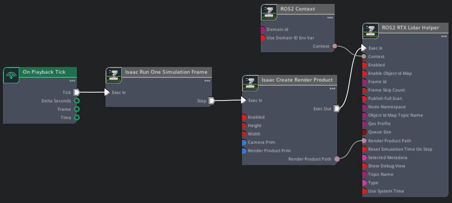
Use the ROS2 RTX Lidar Helper to publish LaserScan data.
Create an On Playback Tick node and connect
Tickto an Isaac Run One Simulation Frame node.Connect the output of Isaac Run One Simulation Frame to an Isaac Create Render Product node. Set its
cameraPrimproperty to the.../sim_lidar/Lidarprim from the sensor you created earlier.Create a ROS2 RTX Lidar Helper node. Set
frameIdtosim_lidar,topicNametoscan, andtypetolaser_scan.Connect the outputs of Isaac Create Render Product to the input of ROS2 RTX Lidar Helper.
Create a ROS2 Context node and connect it to the ROS2 RTX Lidar Helper node.
Script Editor Code
import omni.graph.core as og
import omni.usd
from pxr import Sdf

ROBOT_PRIM = "/dd100"
CHASSIS_LINK = f"{ROBOT_PRIM}/Geometry/base_link/chassis_link"
LIDAR_SENSOR_PRIM = f"{CHASSIS_LINK}/sim_lidar/Lidar"
GRAPH_PATH = f"{CHASSIS_LINK}/sim_lidar/scan"

stage = omni.usd.get_context().get_stage()
if stage.GetPrimAtPath(GRAPH_PATH):
    stage.RemovePrim(GRAPH_PATH)

keys = og.Controller.Keys

og.Controller.edit(
    {"graph_path": GRAPH_PATH, "evaluator_name": "execution"},
    {
        keys.CREATE_NODES: [
            ("OnPlaybackTick", "omni.graph.action.OnPlaybackTick"),
            ("RunOneFrame", "isaacsim.core.nodes.OgnIsaacRunOneSimulationFrame"),
            ("CreateRenderProduct", "isaacsim.core.nodes.IsaacCreateRenderProduct"),
            ("Context", "isaacsim.ros2.bridge.ROS2Context"),
            ("LidarHelper", "isaacsim.ros2.bridge.ROS2RtxLidarHelper"),
        ],
        keys.SET_VALUES: [
            ("CreateRenderProduct.inputs:cameraPrim", [Sdf.Path(LIDAR_SENSOR_PRIM)]),
            ("LidarHelper.inputs:topicName", "scan"),
            ("LidarHelper.inputs:type", "laser_scan"),
            ("LidarHelper.inputs:frameId", "sim_lidar"),
        ],
        keys.CONNECT: [
            ("OnPlaybackTick.outputs:tick", "RunOneFrame.inputs:execIn"),
            ("RunOneFrame.outputs:step", "CreateRenderProduct.inputs:execIn"),
            ("CreateRenderProduct.outputs:execOut", "LidarHelper.inputs:execIn"),
            ("CreateRenderProduct.outputs:renderProductPath", "LidarHelper.inputs:renderProductPath"),
            ("Context.outputs:context", "LidarHelper.inputs:context"),
        ],
    },
)
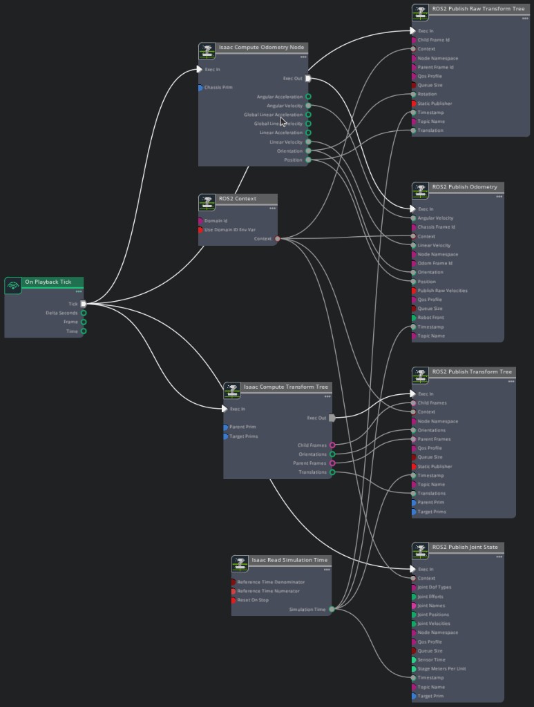
This ActionGraph publishes joint state and odometry data, broadcasts the odom → base_link transform, and publishes a static transform for the sim_lidar sensor frame.
Create an On Playback Tick node.
Create a ROS2 Publish Joint State node. Set
targetPrimto/dd100/Geometry/base_link/chassis_linkandtopicNametoplatform/joint_states.Create an Isaac Compute Odometry Node and set
chassisPrimto/dd100/Geometry/base_link/chassis_link.Create a ROS2 Publish Odometry node and set
topicNameandodomFrameIdtoodom.Create a ROS2 Publish Raw Transform Tree node and set
childFrameIdtobase_linkandparentFrameIdtoodom.Create an Isaac Compute Transform Tree node. Set
parentPrimto/dd100/Geometry/base_link/chassis_linkandtargetPrimsto/dd100/Geometry/base_link/chassis_link/sim_lidar.Create a ROS2 Publish Transform Tree node. Set
topicNametotf_staticand enablestaticPublisher. Connect the outputs of Isaac Compute Transform Tree (childFrames,orientations,parentFrames,translations) to the corresponding inputs of ROS2 Publish Transform Tree. This publishes the static transform frombase_linktosim_lidarso that Nav2 can use the LiDAR data.Connect each matching output from Isaac Compute Odometry Node to the corresponding inputs of ROS2 Publish Odometry and ROS2 Publish Raw Transform Tree.
Create Isaac Read Simulation Time and ROS2 Context nodes and connect them to each of the other nodes.
Script Editor Code
import omni.graph.core as og
import omni.usd
from pxr import Sdf

ROBOT_PRIM = "/dd100"
CHASSIS_LINK = f"{ROBOT_PRIM}/Geometry/base_link/chassis_link"
SIM_LIDAR = f"{CHASSIS_LINK}/sim_lidar"
GRAPH_PATH = f"{CHASSIS_LINK}/joint_states"

stage = omni.usd.get_context().get_stage()
if stage.GetPrimAtPath(GRAPH_PATH):
    stage.RemovePrim(GRAPH_PATH)

keys = og.Controller.Keys

og.Controller.edit(
    {"graph_path": GRAPH_PATH, "evaluator_name": "execution"},
    {
        keys.CREATE_NODES: [
            ("OnPlaybackTick", "omni.graph.action.OnPlaybackTick"),
            ("ReadSimTime", "isaacsim.core.nodes.IsaacReadSimulationTime"),
            ("Context", "isaacsim.ros2.bridge.ROS2Context"),
            ("PublishJointState", "isaacsim.ros2.bridge.ROS2PublishJointState"),
            ("ComputeOdom", "isaacsim.core.nodes.IsaacComputeOdometry"),
            ("PublishOdom", "isaacsim.ros2.bridge.ROS2PublishOdometry"),
            ("PublishRawTF", "isaacsim.ros2.bridge.ROS2PublishRawTransformTree"),
            ("ComputeTransformTree", "isaacsim.core.nodes.IsaacComputeTransformTree"),
            ("PublishTF", "isaacsim.ros2.bridge.ROS2PublishTransformTree"),
        ],
        keys.SET_VALUES: [
            ("PublishJointState.inputs:targetPrim", [Sdf.Path(CHASSIS_LINK)]),
            ("PublishJointState.inputs:topicName", "platform/joint_states"),
            ("ComputeOdom.inputs:chassisPrim", [Sdf.Path(CHASSIS_LINK)]),
            ("PublishOdom.inputs:topicName", "odom"),
            ("PublishOdom.inputs:odomFrameId", "odom"),
            ("PublishRawTF.inputs:childFrameId", "base_link"),
            ("PublishRawTF.inputs:parentFrameId", "odom"),
            ("ComputeTransformTree.inputs:parentPrim", Sdf.Path(CHASSIS_LINK)),
            ("ComputeTransformTree.inputs:targetPrims", [Sdf.Path(SIM_LIDAR)]),
            ("PublishTF.inputs:topicName", "tf_static"),
            ("PublishTF.inputs:staticPublisher", True),
        ],
        keys.CONNECT: [
            ("OnPlaybackTick.outputs:tick", "PublishJointState.inputs:execIn"),
            ("ReadSimTime.outputs:simulationTime", "PublishJointState.inputs:timeStamp"),
            ("OnPlaybackTick.outputs:tick", "ComputeOdom.inputs:execIn"),
            ("ComputeOdom.outputs:execOut", "PublishOdom.inputs:execIn"),
            ("ComputeOdom.outputs:angularVelocity", "PublishOdom.inputs:angularVelocity"),
            ("ComputeOdom.outputs:linearVelocity", "PublishOdom.inputs:linearVelocity"),
            ("ComputeOdom.outputs:orientation", "PublishOdom.inputs:orientation"),
            ("ComputeOdom.outputs:position", "PublishOdom.inputs:position"),
            ("ReadSimTime.outputs:simulationTime", "PublishOdom.inputs:timeStamp"),
            ("OnPlaybackTick.outputs:tick", "PublishRawTF.inputs:execIn"),
            ("ComputeOdom.outputs:orientation", "PublishRawTF.inputs:rotation"),
            ("ComputeOdom.outputs:position", "PublishRawTF.inputs:translation"),
            ("ReadSimTime.outputs:simulationTime", "PublishRawTF.inputs:timeStamp"),
            ("OnPlaybackTick.outputs:tick", "ComputeTransformTree.inputs:execIn"),
            ("ComputeTransformTree.outputs:execOut", "PublishTF.inputs:execIn"),
            ("ComputeTransformTree.outputs:childFrames", "PublishTF.inputs:childFrames"),
            ("ComputeTransformTree.outputs:orientations", "PublishTF.inputs:orientations"),
            ("ComputeTransformTree.outputs:parentFrames", "PublishTF.inputs:parentFrames"),
            ("ComputeTransformTree.outputs:translations", "PublishTF.inputs:translations"),
            ("ReadSimTime.outputs:simulationTime", "PublishTF.inputs:timeStamp"),
            ("Context.outputs:context", "PublishJointState.inputs:context"),
            ("Context.outputs:context", "PublishOdom.inputs:context"),
            ("Context.outputs:context", "PublishRawTF.inputs:context"),
            ("Context.outputs:context", "PublishTF.inputs:context"),
        ],
    },
)
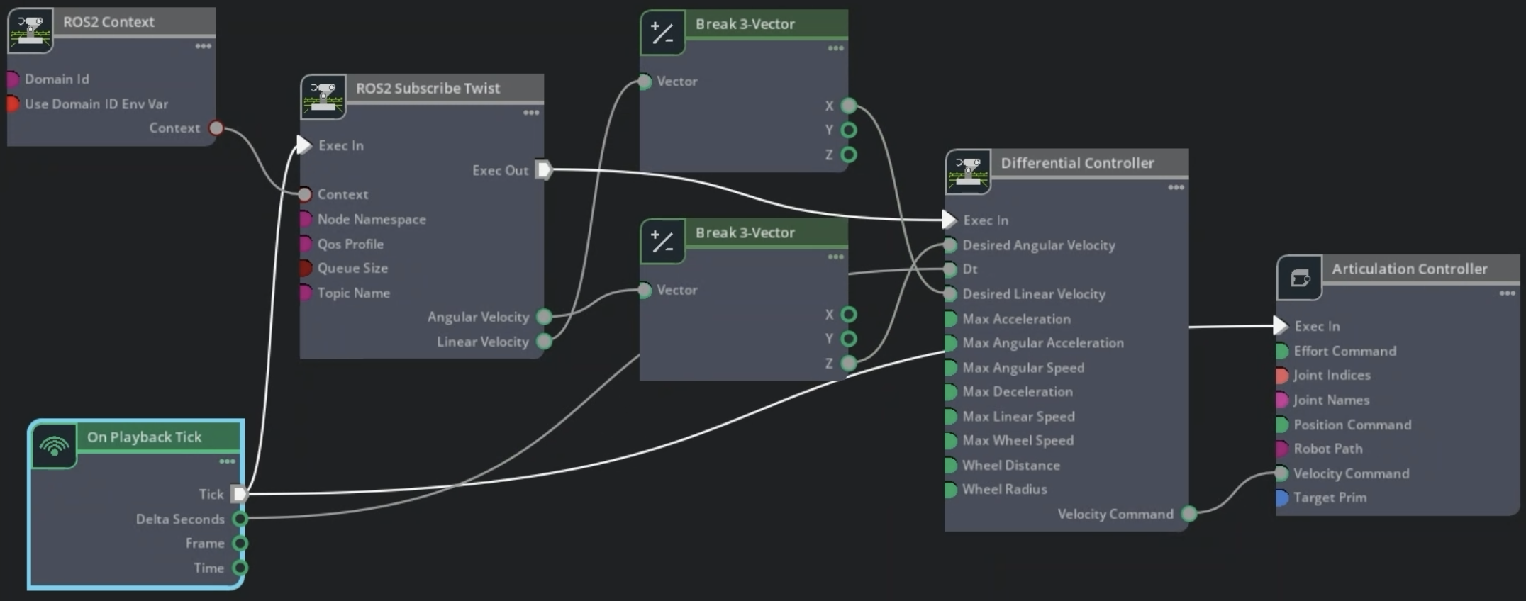
This ActionGraph subscribes to the cmd_vel topic and drives the robot’s wheels.
Create an On Playback Tick node.
Create a ROS2 Subscribe Twist node and set
topicNametocmd_vel.Because the robot is flat and you only need forward speed and yaw, use two Break 3-Vector nodes to extract the
Xcomponent of the linear velocity and theZcomponent of the angular velocity.Create a Differential Controller node with the following properties:
Field
Value
Max Angular Speed
1.0
Max Linear Speed
1.3
Wheel Distance
0.45
Wheel Radius
0.1
Create an Articulation Controller node. Set jointNames to
front_left_wheel_jointandfront_right_wheel_joint, and targetPrim to/dd100.Create a ROS2 Context node and connect it to the ROS2 Subscribe Twist node.
Connect the pipeline: ROS2 Subscribe Twist outputs through the Break 3-Vector nodes into Differential Controller, then into Articulation Controller.
Script Editor Code
import omni.graph.core as og
import omni.usd
from pxr import Sdf

ROBOT_PRIM = "/dd100"
CHASSIS_LINK = f"{ROBOT_PRIM}/Geometry/base_link/chassis_link"
GRAPH_PATH = f"{CHASSIS_LINK}/cmd_vel"

stage = omni.usd.get_context().get_stage()
if stage.GetPrimAtPath(GRAPH_PATH):
    stage.RemovePrim(GRAPH_PATH)

keys = og.Controller.Keys

og.Controller.edit(
    {"graph_path": GRAPH_PATH, "evaluator_name": "execution"},
    {
        keys.CREATE_NODES: [
            ("OnPlaybackTick", "omni.graph.action.OnPlaybackTick"),
            ("Context", "isaacsim.ros2.bridge.ROS2Context"),
            ("SubscribeTwist", "isaacsim.ros2.bridge.ROS2SubscribeTwist"),
            ("BreakLinVel", "omni.graph.nodes.BreakVector3"),
            ("BreakAngVel", "omni.graph.nodes.BreakVector3"),
            ("DiffController", "isaacsim.robot.wheeled_robots.DifferentialController"),
            ("ArtController", "isaacsim.core.nodes.IsaacArticulationController"),
        ],
        keys.SET_VALUES: [
            ("SubscribeTwist.inputs:topicName", "cmd_vel"),
            ("DiffController.inputs:maxAngularSpeed", 1.0),
            ("DiffController.inputs:maxLinearSpeed", 1.3),
            ("DiffController.inputs:wheelDistance", 0.45),
            ("DiffController.inputs:wheelRadius", 0.1),
            ("ArtController.inputs:jointNames", ["front_left_wheel_joint", "front_right_wheel_joint"]),
            ("ArtController.inputs:targetPrim", [Sdf.Path(ROBOT_PRIM)]),
        ],
        keys.CONNECT: [
            ("OnPlaybackTick.outputs:tick", "SubscribeTwist.inputs:execIn"),
            ("OnPlaybackTick.outputs:deltaSeconds", "DiffController.inputs:dt"),
            ("SubscribeTwist.outputs:execOut", "DiffController.inputs:execIn"),
            ("SubscribeTwist.outputs:linearVelocity", "BreakLinVel.inputs:tuple"),
            ("BreakLinVel.outputs:x", "DiffController.inputs:linearVelocity"),
            ("SubscribeTwist.outputs:angularVelocity", "BreakAngVel.inputs:tuple"),
            ("BreakAngVel.outputs:z", "DiffController.inputs:angularVelocity"),
            ("DiffController.outputs:velocityCommand", "ArtController.inputs:velocityCommand"),
            ("OnPlaybackTick.outputs:tick", "ArtController.inputs:execIn"),
            ("Context.outputs:context", "SubscribeTwist.inputs:context"),
        ],
    },
)
With the ActionGraphs created, you can validate in a ROS 2 sourced terminal that the expected data appears on the ROS 2 topics:
Select Play in Isaac Sim.
Verify that you receive the following topics:
ros2 topic list
Expected output:
/cmd_vel
/platform/joint_states
/odom
/parameter_events
/rosout
/scan
/tf
/tf_static
To visualize the full TF tree:
Make sure the robot description launch file from the Generate the Robot Description step is still running. If it was closed, relaunch it:
ros2 launch clearpath_platform_description description.launch.py -- setup_path:=$ROBOT_PARAMS
ros2 launch clearpath_platform_description description.launch.py -- setup_path:=$env:ROBOT_PARAMS
Use
view_framesfrom thetf2_toolspackage to generate the TF tree PDF.ros2 run tf2_tools view_frames
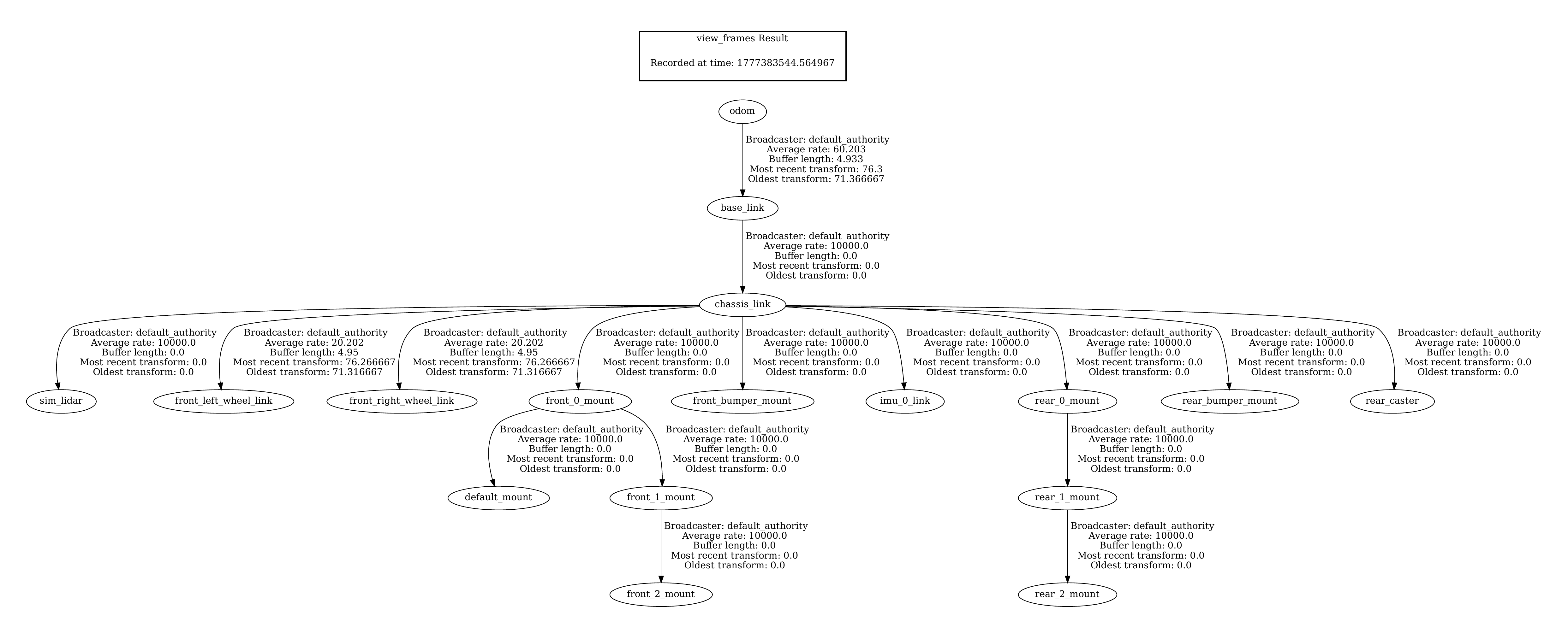
Once the TF tree PDF has been generated, you can close the robot description launch terminal.
To run a test to verify that the cmd_vel ActionGraph is working properly:
Add a ground plane by clicking Create > Physics > Ground Plane and click Play.
In a ROS 2 sourced terminal, publish a twist message to the
/cmd_veltopic (see below).Verify that the robot moves around the environment.
ros2 topic pub /cmd_vel geometry_msgs/Twist "{'linear': {'x': 1, 'y': 0.0, 'z': 0.0}, 'angular': {'x': 0.0, 'y': 0.0, 'z': 1.0}}" --once
Save the stage after verifying the robot moves. You can delete the ground plane or move it outside the default prim before saving.
Add Automatic Namespace Attributes#
Adding isaac:namespace attributes ensures topic names are descriptive and scales cleanly when multiple robots share a scene. For full details, see the Automatic ROS 2 Namespace Generation tutorial.
For each prim listed in the table below, add the isaac:namespace attribute:
Select the prim.
Click Add in the Property panel.
Navigate to Isaac > Namespace.
Set the value to the corresponding Namespace Value from the table.
Prim |
Namespace Value |
|---|---|
|
|
|
|
|
|
Now, after selecting Play, run:
ros2 topic list
Expected output, with the namespaced topics:
/dd100_0000/cmd_vel
/dd100_0000/platform/joint_states
/dd100_0000/odom
/dd100_0000/sim_lidar/scan
/dd100_0000/tf
/dd100_0000/tf_static
/parameter_events
/rosout
Save the stage.
Simulation Scene#
Start by loading a larger warehouse environment.
Create a new stage with
CTRL+N.Drag in a warehouse environment from the Content browser at Isaac Sim > Environments > Simple_Warehouse > full_warehouse.usd.
Zero out the Translate components.
Drag the
dd100_with_sensors.usdUSD file onto the stage.Set the Translate components to
(-3.0, 6.0, 0.025)and the Orient components to(0.0, 0.0, 90.0).
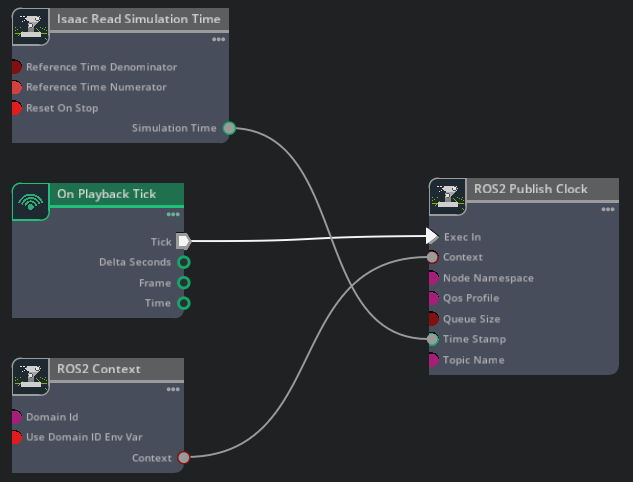
Next, add a clock ActionGraph. This should be added to the final scene instead of in the robot directly so that adding multiple robots does not publish duplicate clock messages.
Create a new ActionGraph by right-clicking on the stage and selecting Create > Action Graph. Rename it to
clock.Add the following nodes: On Playback Tick, ROS2 Context, Isaac Read Simulation Time, and ROS2 Publish Clock.
Connect them together as shown below.
Script Editor Code
import omni.graph.core as og
import omni.usd

GRAPH_PATH = "/World/clock"

stage = omni.usd.get_context().get_stage()
if stage.GetPrimAtPath(GRAPH_PATH):
    stage.RemovePrim(GRAPH_PATH)

keys = og.Controller.Keys

og.Controller.edit(
    {"graph_path": GRAPH_PATH, "evaluator_name": "execution"},
    {
        keys.CREATE_NODES: [
            ("OnPlaybackTick", "omni.graph.action.OnPlaybackTick"),
            ("Context", "isaacsim.ros2.bridge.ROS2Context"),
            ("ReadSimTime", "isaacsim.core.nodes.IsaacReadSimulationTime"),
            ("PublishClock", "isaacsim.ros2.bridge.ROS2PublishClock"),
        ],
        keys.CONNECT: [
            ("OnPlaybackTick.outputs:tick", "PublishClock.inputs:execIn"),
            ("ReadSimTime.outputs:simulationTime", "PublishClock.inputs:timeStamp"),
            ("Context.outputs:context", "PublishClock.inputs:context"),
        ],
    },
)
Save the stage as
dd100_warehouse_navigation.usd.
Occupancy Map#
Nav2 requires an occupancy map of the environment to plan collision-free paths. Generate one using the Occupancy Map Generator extension. For a more detailed walkthrough with screenshots, refer to the Occupancy Map section of the ROS 2 Navigation tutorial.
Switch to a Top camera view ( Camera dropdown at the upper-left of the viewport > Top ).
Open Tools > Robotics > Occupancy Map.
Set the origin to
(0.0, 0.0, 0.0). Set the Lower Bound Z to0.2and the Upper Bound Z to0.62.Select the warehouse root prim in the Stage Tree, then click BOUND SELECTION in the Occupancy Map extension to auto-fit the map bounds.
Click CALCULATE, then VISUALIZE IMAGE.
Click Save YAML and save as
dd100_warehouse_navigation.yaml.Click Save Image and save as
dd100_warehouse_navigation.pngin the same directory as the YAML file.
The generated occupancy map should look similar to the following:
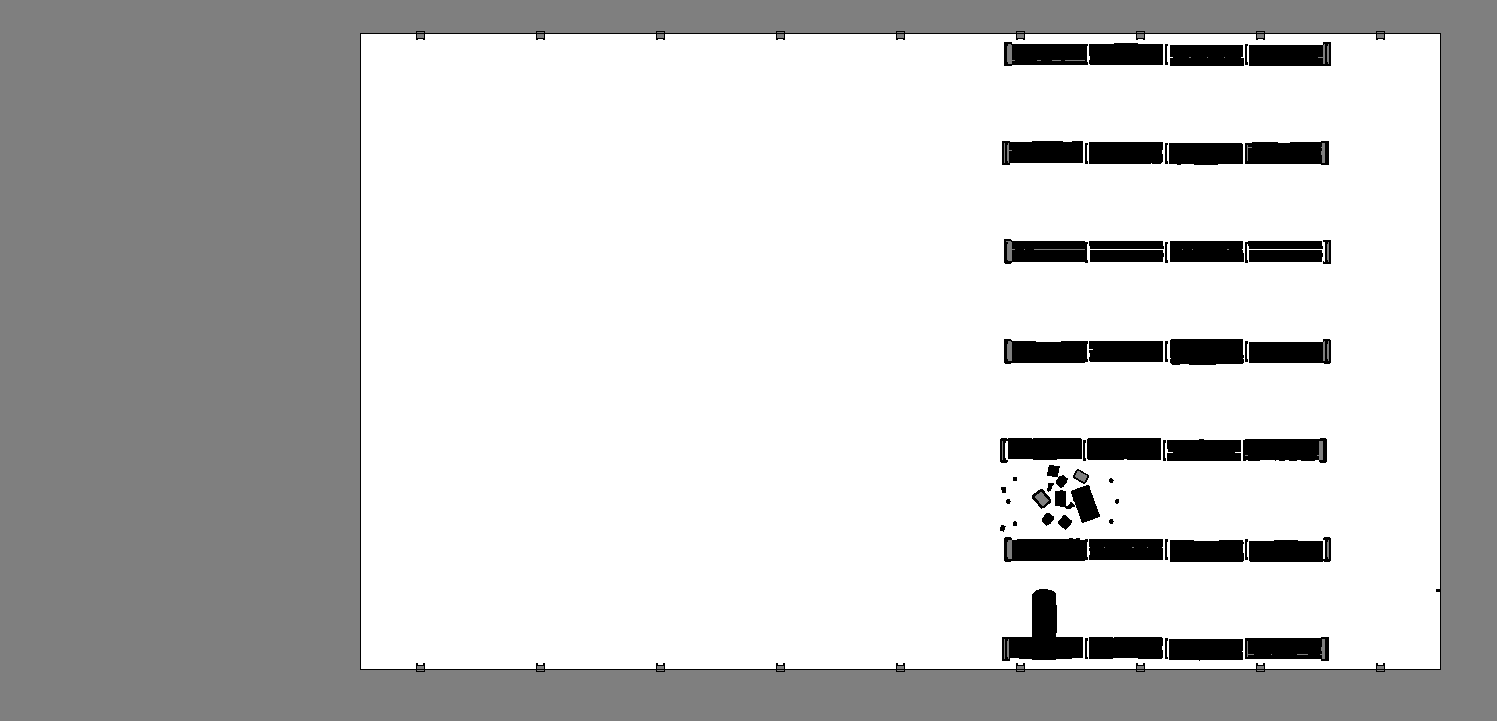
Occupancy map generated from the full warehouse environment. The robot is not visible because you set the Lower Bound Z to 0.2 (above the robot).#
Running Nav2#
Control the robot using the Nav2 stack. Nav2 is a ROS 2-based navigation stack for mobile robots. It provides a set of tools and libraries for building and running navigation systems.
Click Play in Isaac Sim.
In a ROS-sourced terminal, launch the full navigation stack. This starts
robot_state_publisher, Nav2, and RViz in a single command. The Nav2 parameters are pre-configured in theisaacsim_clearpath_nav2package.ros2 launch isaacsim_clearpath_nav2 clearpath_navigation.launch.py \ map:=/path/to/dd100_warehouse_navigation.yaml \ namespace:=dd100_0000
ros2 launch isaacsim_clearpath_nav2 clearpath_navigation.launch.py `
    map:=C:\path\to\dd100_warehouse_navigation.yaml `
    namespace:=dd100_0000
When
rvizopens, set the robot’s initial pose by clicking the 2D Pose Estimate button at the top of the window and clicking to place the pose estimate at the robot’s current location on the map.After Adaptive Monte Carlo Localization (AMCL) localizes the robot, use the Nav2 Goal button to send a navigation goal. Place the goal above the equipment in the aisle.
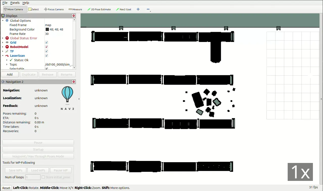
Setting the initial pose estimate and Nav2 goal in RViz, then watching the robot navigate toward the goal in Isaac Sim.#
Because the robot has a LiDAR and Nav2 actively recomputes paths when obstacles appear, you can interact with the robot through the environment.
Interactive robot response based on environmental disturbances.#
Summary#
In this tutorial, you:
Imported the Clearpath Dingo-D URDF robot model into Isaac Sim using the URDF Importer Extension.
Incorporated physics and collision properties, including joint damping and physics materials for the drive wheels and caster.
Attached a RealSense D455 depth camera and a SICK microScan3 LiDAR sensor to the robot model.
Built OmniGraph publishers and subscribers to connect the robot to the ROS 2 network (joint states, odometry, TF, laser scan, clock, and cmd_vel).
Integrated the Nav2 navigation stack to autonomously move the robot between two points in a warehouse environment.