ROS 2 Generic Server and Client#
Learning Objectives#
In this example, you learn how to use Isaac Sim to:
Receive a ROS2 message of any type and respond using generic server nodes
Send a ROS2 message of any type and receive the response using generic client nodes
Getting Started#
If sourcing ROS 2 is a part of your .bashrc then Isaac Sim can be run directly.
Prerequisite
Complete ROS 2 Installation.
If using multiple systems, set the
FASTRTPS_DEFAULT_PROFILES_FILEenvironment variable, as per instructions in ROS 2 Installation before launching Isaac Sim, and set it in any terminal where ROS messages will be sent or received and the ROS 2 Extension is enabled.
ROS 2 Messages Types#
See ROS 2 Generic Publisher and Subscriber for background information about ROS2 topics and message types. Generic services (server and client) build on a similar communication style. Generic server and client nodes allow sending and receiving of any ROS messages when the underlying message type and ROS package are defined. To review all existing services in your environment use the following:
ros2 interface list --only-srvs
You can review the actual service configuration in your ROS distro under the share/packageName/srv/serviceName subdirectory (for example, share/std_srvs/srv/SetBool for std_srvs/srv/SetBool service).
The service configuration file is comprised of two sections:
The first section defines the request message sent by a client and received by the server.
The second section defines the response message that is sent by the server and received by the client.
Generic Server#
Basic Methodology:
Go to Window > Graph Editors > Action Graph to create an Action Graph.
Add (and connect) the following OmniGraph nodes into the Action Graph:
On Playback Tick node to execute other graph nodes every simulation frame.
ROS2 Context node to create a context using either the given Domain ID or the
ROS_DOMAIN_IDenvironment variable.ROS2 Service Server Request node to receive a ROS2 service request message of any type.
ROS2 Service Server Response node to respond a ROS2 service request message of any type.
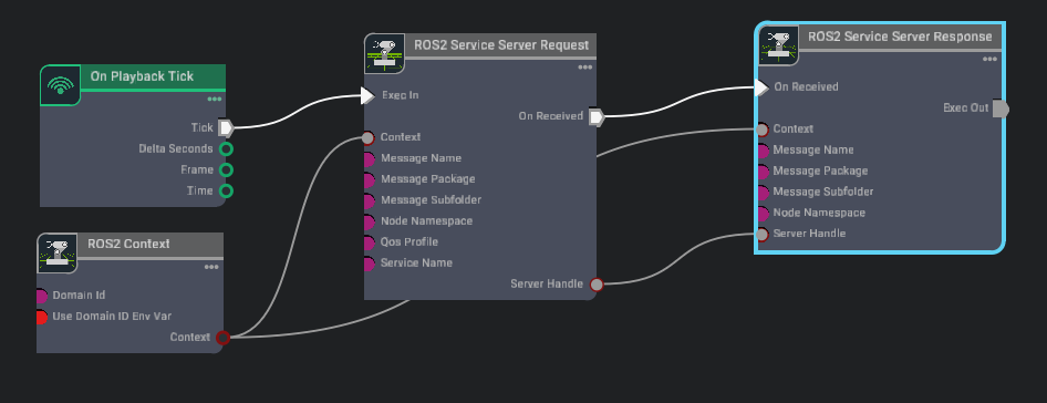
Make the following connections:
Connecting the
Server Handleoutput property of the ROS2 Service Server Request toServer Handleinput property of ROS2 Service Server Response ensures that the two nodes share the same server.Connecting the
On receivedoutput execution property of the ROS2 Service Server Request toOn receivedinput property of ROS2 Service Server Response ensures that the server sends responses only when a request is received.
After connecting playback tick node to the request node and the context node to both request and response nodes, verify that the graph is similar to:
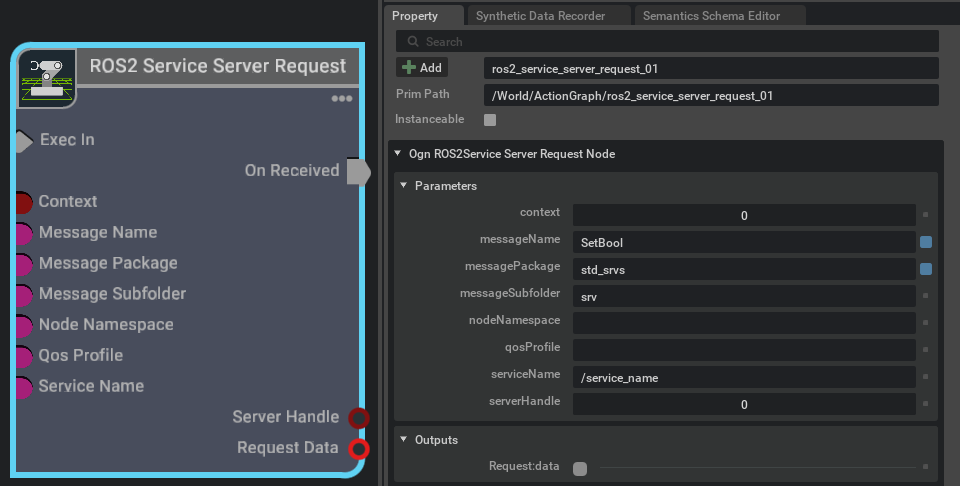
- In the node Property panel define the message type using this pattern:
messagePackage / messageSubfolder / messageName. When a valid (existing) message type is defined, the node will reconfigure its input/output attributes to set the values to be received/sent.
Note
You must enter the same message fields for both ROS2 Service Server Request and ROS2 Service Server Response nodes that are connected through their server handle. For example, for a service such as
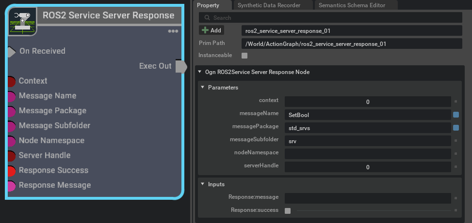
std_srvs/srv/SetBool, themessagePackagewill bestd_srvs,messageSubfolderwill be srv, andmessageNamemust beSetBool.The outputs of the ROS2 Service Server Request will include the service request fields whereas the inputs of the ROS2 Service Server Response will include the service response fields.
Hint
It is not necessary to play the simulation to (re)configure the node’s input attributes for different message types.
Example of how the ROS2 Service Server Request node outputs will reconfigure to include the Request fields:
Example of how the ROS2 Service Server Response node inputs will reconfigure to include the Response fields:
- In the node Property panel define the message type using this pattern:
You can also modify the default Service Name property of ROS2 Service Server Request node in the Property panel of the node. The client must use the same name to communicate with this server.
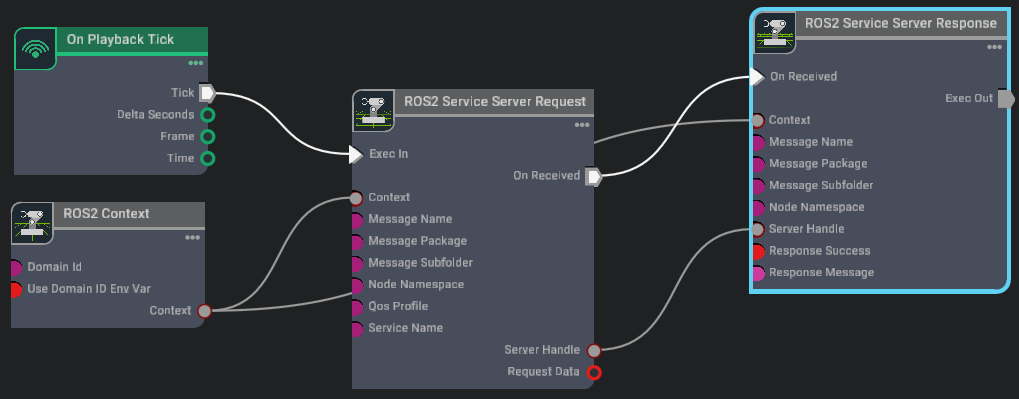
Example:
After following the above step the Final configuration of our example server is the following:
Play the simulation. The server must be ready to receive requests.
Use your values for the input fields of the ROS2 Service Server Response, with a sample message to be sent back to the client and status bool data.
In a separate terminal, source ROS, and issue the following command. This will send a request of type
example_interfaces/srv/SetBoolfrom a ROS client with aTruebool data field to the server with the service name of/service_name.ros2 service call /service_name std_srvs/srv/SetBool "{data: true}"
Validate that it returns the server response you provided in the server node, for example:
requester: making request: std_srvs.srv.SetBool_Request(data=True)

response:
std_srvs.srv.SetBool_Response(success=True, message='Sample response message')
where
Sample response messageis the sample message you entered in theResponse Messageof the ROS2 Service Server Response node.
Generic Client#
Basic Methodology:
To add a generic client
Go to Window > Graph Editors > Action Graph to create an Action Graph.
Add (and connect) the following OmniGraph nodes into the Action Graph:
On Playback Tick node to execute other graph nodes every simulation frame.
ROS2 Context node to create a context using either the given Domain ID or the
ROS_DOMAIN_IDenvironment variable.ROS2 Service Client node to send a ROS2 request message of any type and receive a response message of any type.
- In the node Property panel define the message type following this pattern:
messagePackage / messageSubfolder / messageName. ROS2 Service Client node inputs and outputs will reconfigure according to the service configuration selected by you. The inputs include the service request fields. The outputs include the response field. For instance, for a service, such as
std_srvs/srv/SetBool, the messagePackage isstd_srvs,messageSubfolderissrv, andmessageNamemust beSetBool. When a valid and existing message type is defined, the node will reconfigure its input/outputs attributes. Below is an example of how the ROS2 Service Client node inputs/outputs reconfigure to include the Request/Response fields: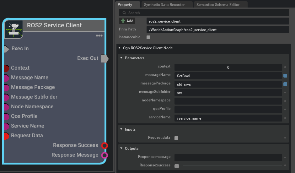
- In the node Property panel define the message type following this pattern:
After you play the simulation the client will start making requests according to its input data/fields. The server response is accessible from the node’s outputs.
Example:
Reconfigure the previous OmniGraph example to include the client node in the same graph. This will enable you to send requests from within the OmniGraph using the client node instead of the terminal.
Create a graph as follows:
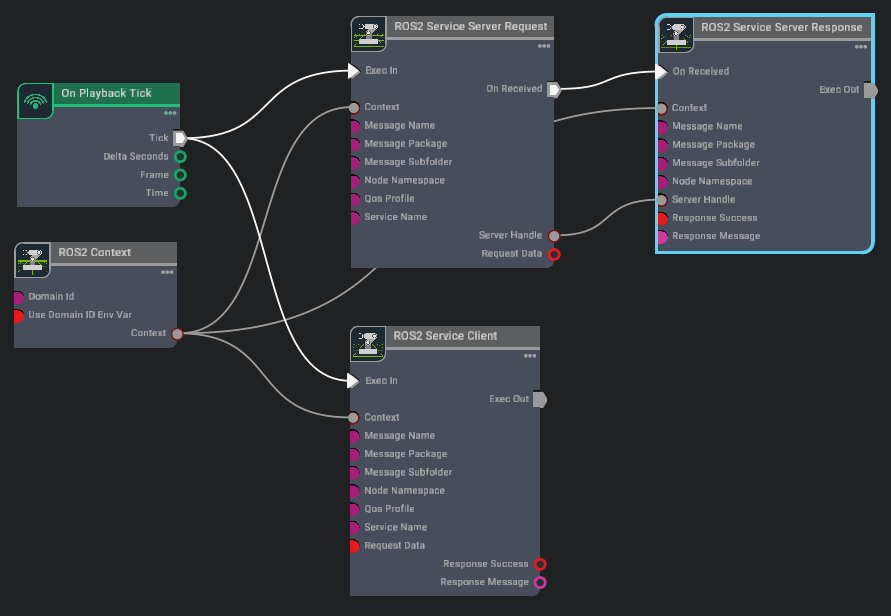
Play the simulation. The client and server nodes are both sending and receiving request and response messages.
Select the ROS2 Service Server Response and modify the response message of the server in the
Response Messagefield of the input.Select the ROS2 Service Client node and verify that the client node is receiving the response you provided in the server node.
Summary#
In this tutorial you learned how to reconfigure the generic server and client nodes to send and receive any ROS2 messages in Isaac Sim.
Next Steps#
Continue on to the next tutorial, ROS 2 Service for Manipulating Prims Attributes to learn how to create ROS 2 services to list prims and their attributes, as well as to read and write a specific prim attribute.