Robot Wizard Tutorial#
This tutorial is a step-by-step guide for using the Robot Wizard to create a mock robot that contains a fixed base, a prismatic joint, and a revolute joint.
Load the prepared file for this tutorial onto stage. Go to Isaac/Samples/Rigging/RobotWizard/ and open the original file for raw_blocks.usd.
For more in-depth explanation about the Wizard, refer to Robot Wizard [Beta].
If the Wizard window is not already open, open it from Window > Robot Wizard. If you don’t observe the wizard under the Window menu, go to the Window > Extensions and enable Isaac Sim Robot Wizard.
Instructions#
Add Robot Page#
Select Configure a Robot on Stage.
Select custom in the dropdown list for Robot Type.
Give your robot a name. The name will be used as the robot’s parent prim name on stage.
If the robot prim is not already populated in the Select Robot Parent Xform field, click on the dropper and select World from the stage popup.
Click Prepare Files to complete this page.
Prepare Files#
Indicate the root folder to save the robot files. You can also modify the robot name here, if needed, for creating a new folder.
Check the Save a Copy in Robot Root Folder for the current stage and keep the default filepath when that field appears.
Click Next to move to the next page.
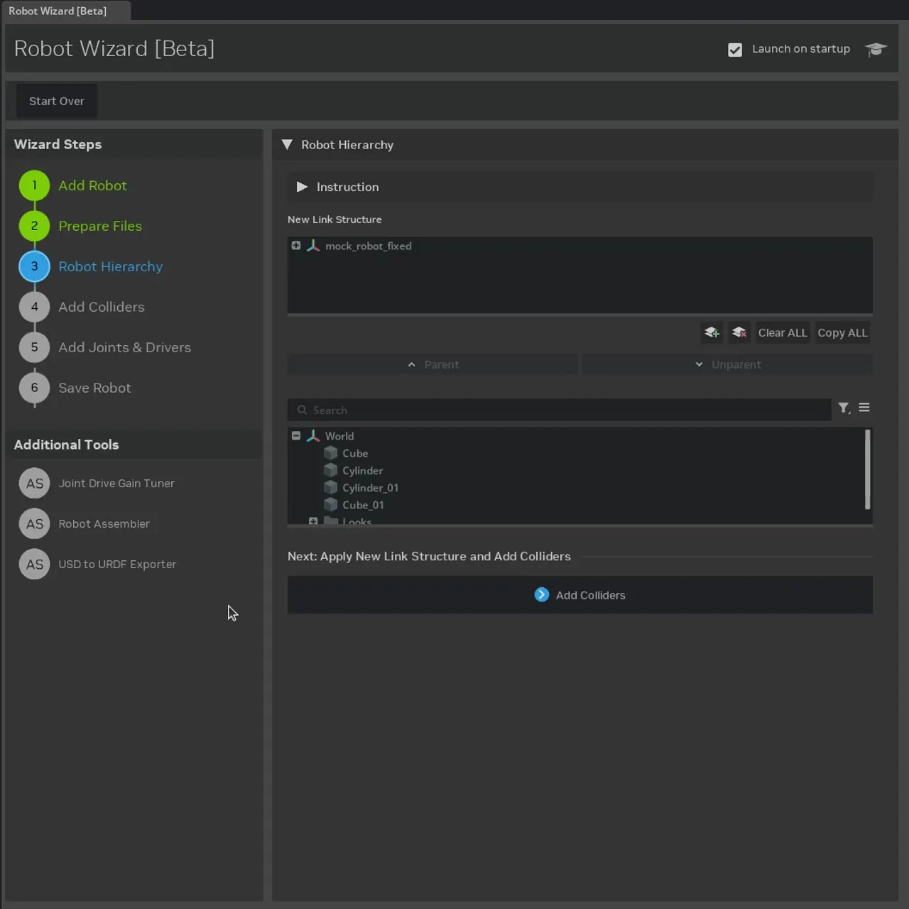
Robot Hierarchy#
Add a new link inside the New Links Structure window and name it “<robot_name>/link3”.
Put Cube and Cone under
link1, Cylinder underlink2, andCylinder_01andCube_01underlink3.Click Add Colliders to finish this page.
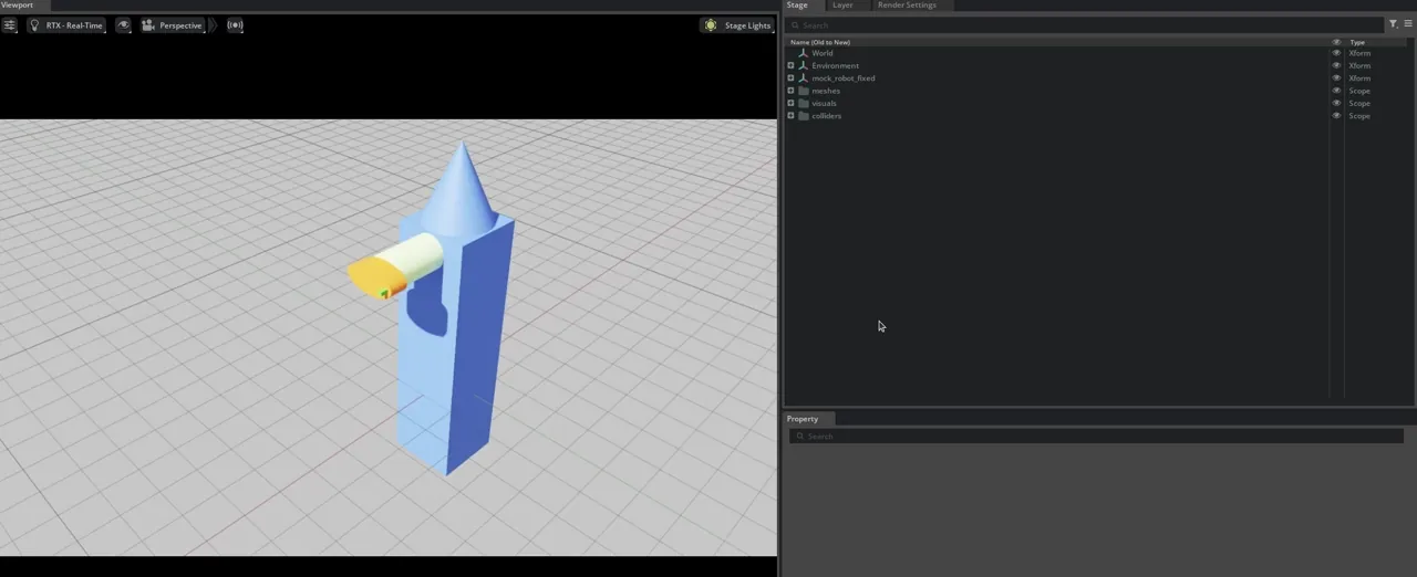
Note
You are no longer looking at the original raw_blocks.usd file on stage. Instead, a new stage is opened with a robot that’s organized in the link structure you organized in the Robot Hierarchy page. This might look a little strange in the viewport.
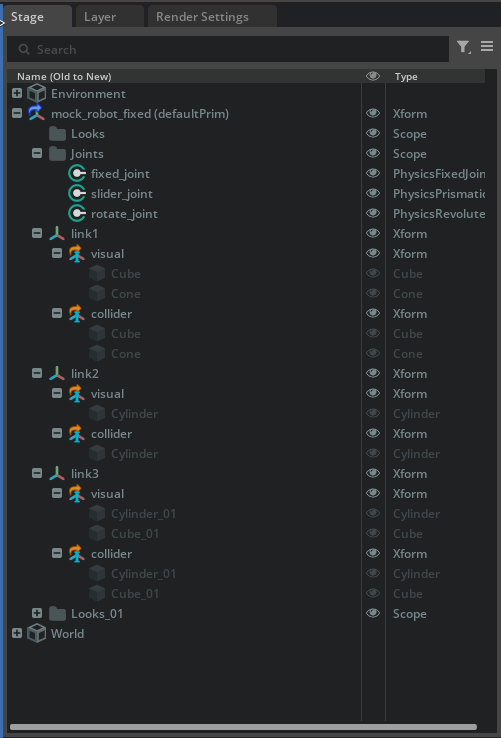
Take a look at the Stage window, verify that in addition to the new robot with the new structure, there are also three new “Scopes” added to the stage:
meshes scope contains the original meshes from the
raw_blocks.usdfile. Each link is a separate mesh, and each mesh has a (0,0,0) origin, that is why there are two copies of each shape, some of them appearing to be clustered in the center of the grid.visuals scope contains the visual meshes for each link. They are references pointing towards meshes inside the “meshes” scope that are being used for visual purposes.
colliders scope contains the collision meshes for each link. They are also references, but pointing to the meshes inside the “meshes” scope that are used for collision detections. For basic shapes, the visual and collider meshes are often the same. For complex shapes, it is computationally performant to use an approximated version of the visual mesh, such as the bounding volume or convex hull. This allows for faster physics computation while retaining the visual accuracy.
Verify that the main robot prim contains the links as its immediate children, and that each link prims contains the visual and collider meshes as its immediate children. Additional scopes (folders) and a placeholder folder for the joints are created to organize the materials.
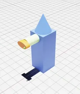
To observe what the new robot looks like without the original meshes distraction, hide the “meshes”, “visuals”, and “colliders” scopes.
Add Colliders#
For this particular asset, where the shapes are basic, there’s nothing to do on this page. If you are configuring a robot with more complex shapes, you can modify the collision approximation on the right hand column for level of accuracy.
Click Add Joints & Drives to move on to the next page.
Note
Everything prior to adding the colliders are considered fundamental to the definition of the robot, therefore are saved in the base layer. Rigid Body APIs, Collision APIs, and Joint and Drive APIs are specifically adding properties and setting for physics simulation, and therefore are applied to the physics sublayer of the robot. To inspect the layers, click on the Layers tab next to the Stage tab in the main Isaac Sim window. Verify that you are editing the physics layer, which has the base layer included as a sublayer.
Add Joints and Drives#
Click on the Create New Joint button to add a new joint.
Make three joints for this robot. Select Create to add the first two, and Create & Close to add the third.
Joint Name |
Joint Type |
Axis |
Parent Link |
Child Link |
Driver Type |
|---|---|---|---|---|---|
fixed_joint |
Fixed |
— |
— |
<robot_name>/link1 |
— |
slider_joint |
Prismatic |
X |
<robot_name>/link1 |
<robot_name>/link2 |
force |
rotate_joint |
Revolute |
Z |
<robot_name>/link2 |
<robot_name>/link3 |
force |
Update the joint parameters for the
slider_joint ``and ``rotate_joint. Click on the joint name in the table to open the joint settings for the selected joint.
Prismatic joint
set the joint limit to 0 to 3
set the target position to 1
set the stiffness to 1e5 and damping to 2e4
Revolute joint
uncheck the Joint Range is Limited checkbox so that this joint can rotate perpetually
set the target velocity to 100
set the stiffness to 0 to enable pure velocity drive
Click Save Robot to save the robot and move on to the next page.
Verify that the Joints folder is populated with the three created joints. You can confirm the settings for each joint by clicking on the joint name in the stage tree. Then use the property panel to validate the joint and drive parameters.
Save Robot#
Select the “fixed_joint” as the “Articulation Root”.
Select to add a light and physics scene to the main robot file. The ground is optional because the robot has a fixed joint to the world.
Click Save Robot to finish the process.
After saving the robot, all the appropriate USD files are created in the robot root folder. Verify that the viewport has the robot from the main robot file with physics variant applied.
Click play to observe the joints move. Validate that the slider joint moves to a target position and that the revolute joint rotates perpetually.
Final Product Summary#
Here is summary of all the things that were done by the wizard. There is a final product for you to compare against your own results in the Isaac/Samples/Rigging/RobotWizard/final/ folder.
Robot Hierarchy:
There is still a vestigial /World prim on stage, for now, you can manually move the content into the robot prim’s corresponding folders.
Files and Folders created:
robot_root_folder/
├── configurations/
│   └── <robot-name>_robot.usd
│   └── <robot-name>_physics.usd
│   └── <robot-name>_robot.usd
└── <robot-name>.usd
└── stage_copy.usd
APIs applied:
The APIs applied can be found by selecting the prim on stage and examining the properties panel.
robot_prim (RobotAPI)
├── link1 (RigidBodyAPI, LinkAPI)
│   └── visual
│   ├── collider
│       └── <mesh>  (ColliderAPI)
├── link2 (RigidBodyAPI, LinkAPI)
│   └── visual
│   ├── collider
│       └── <mesh>  (ColliderAPI)
├── link3 (RigidBodyAPI, LinkAPI)
│   └── visual
│   ├── collider
│       └── <mesh>  (ColliderAPI)
├── Joints
│   └── fixed_joint (JointAPI, ArticulationRootAPI)
│   └── slider_joint (JointAPI, DriveAPI, JointStateAPI)
│   └── rotate_joint (JointAPI, DriveAPI, JointStateAPI)