Tutorial 13: Rigging a Legged Robot for Locomotion Policy#
The objective of this tutorial is to explain the process of rigging a legged robot to match the configuration specified by the locomotion policy. The isaac sim Policy Controller Class for inference in Isaac Sim is already handling the process of rigging the robot at run time, so this tutorial is only relevant if you want to run the robot policy with an external process like ROS.
Learning Objectives#
In this tutorial, you will walk through the process of rigging a H1 humanoid robot to match the configuration specified by the H1 flat terrain locomotion policy.
Setting initial robot position
Setting joint configuration
Verifying joint configuration
Note
The H1 flat terrain policy environment definition file is available here
Setting Initial Robot Position#
The inital joint position of the robot is specified under robot:init_state:joint_pos section of the environment definition file. The joint names are specified using the .* wildcard.
 1robot:
 2  init_state:
 3    joint_pos:
 4      .*_hip_yaw: 0.0
 5      .*_hip_roll: 0.0
 6      .*_hip_pitch: -0.28
 7      .*_knee: 0.79
 8      .*_ankle: -0.52
 9      torso: 0.0
10      .*_shoulder_pitch: 0.28
11      .*_shoulder_roll: 0.0
12      .*_shoulder_yaw: 0.0
13      .*_elbow: 0.52
14    joint_vel:
15      .*: 0.0
Note
The joint positions are specified in radians, where as in USD, the joint positions are specified in degrees.
To store the initial state of the robot:
Open the
h1.usdfile from the content browser present atIsaac Sim/Robots/Unitree/H1.Create a joint state api for reporting the robot joint position and velocity.
On the top right corner of the stage, select the
funnelicon and clickPhysics Jointsto filter the joint list.
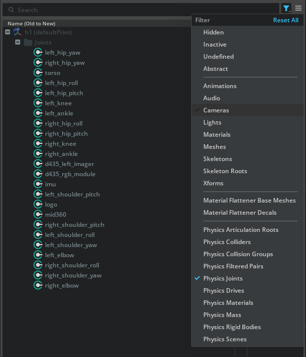
Left click on the first joint (
left_hip_yaw), shift left click on the last joint (right_elbow) to select all the joints.Right click on any selected joint, and click Add > Physics > Joint State Angular to create a joint state API attribute to the joints
Right click on any selected joint, and click Add > Physics > Angular drive to create a joint drive API attribute to the joints
Note
The
Joint State AngularAPI is used to report the joint position and velocity, and theAngular driveAPI is used to drive the joint. If the joint already has aJoint State AngularAPI orAngular driveAPI, you can skip the above steps.
Go to each joint and set the
Target Positionattribute in the joint drive API to the value specified in the environment definition file above on thejoint_posattribute.Similarly, set the
Target Velocityattribute in the joint drive API to the value specified in the environment definition file above on thejoint_velattribute.Make sure you convert the joint positions and velocities from radians to degrees.
Left click on the joint you are changing.
In the property panel below, scroll down to the
Target Positionattribute.Set the
Target Positionattribute to the value specified in the environment definition file above on thejoint_posattributeRepeat the same for the
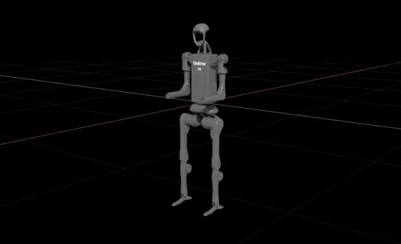
Target VelocityattributePress play.
Verify that you see the robot moving to the initial position specified in the environment definition file. To make the robot start in the initial position when the simulation starts, store the data in the joint state API.
To prevent the robot from falling infinitely, you can add a Fixed Joint between the robot and the world by right clicking on the
/h1/torso_linkand click Create > Physics > Joint > Fixed Joint.
To prevent the joint state API values from resetting, you need to change the simulation setting to not reset the robot state on stop.
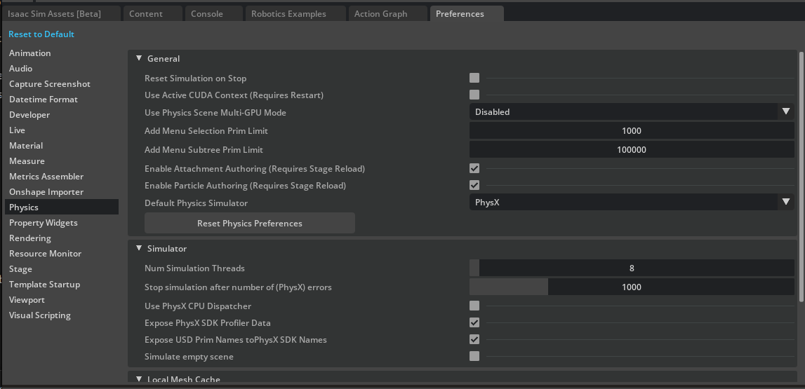
On the top left corner of the stage, click on the Edit and click Preferences.
Select the Preferences window at the bottom, on the left side, click on the Physics tab.
Uncheck Reset Simulation on Stop.
Now you can play the simulation, and when you stop the simulation, the robot will remain in the last state. And when you play the again, the robot will start from the last state.
Delete the Fixed Joint between the robot and the world.
Press Ctrl+S to save the USD file
Check Reset Simulation on Stop again
Setting Joint Configuration#
Set the joint configuration to match the policy’s robot configuration, this maybe different from the value stored in the USD file.
The joint drive configuration is specified under scene:robot:actuators section of the environment definition file.
The snippet below shows the actuator configuration for the H1 robot legs.
 1actuators:k
 2  legs:
 3    class_type: omni.isaac.lab.actuators.actuator_pd:ImplicitActuator
 4    joint_names_expr:
 5    - .*_hip_yaw
 6    - .*_hip_roll
 7    - .*_hip_pitch
 8    - .*_knee
 9    - torso
10    effort_limit: 300
11    velocity_limit: 100.0
12    stiffness:
13      .*_hip_yaw: 150.0
14      .*_hip_roll: 150.0
15      .*_hip_pitch: 200.0
16      .*_knee: 200.0
17      torso: 200.0
18    damping:
19      .*_hip_yaw: 5.0
20      .*_hip_roll: 5.0
21      .*_hip_pitch: 5.0
22      .*_knee: 5.0
23      torso: 5.0
24    armature: null
25    friction: null
The joint_names_expr is a list of joint names to be controlled by the actuator. The class_type is the type of the actuator to be used.
The effort_limit is the maximum effort that can be applied to the joint. The velocity_limit is the maximum velocity that can be applied to the joint.
The stiffness is the stiffness of the joint. The damping is the damping of the joint. The armature is the armature of the joint. The friction is the friction of the joint.
To set the joint configurations:
Left click on a joint such as
left_hip_yawfor example.In the property panel, scroll down to
joint driveattribute, and set thestiffness,dampingto the values specified in the environment definition file.
Note
Remember to convert stiffness and damping to degrees.
The USD file stiffness is in \(\frac{Kg \cdot m^2}{Deg \cdot s^2}\) and the damping is in \(\frac{Kg \cdot m^2}{Deg \cdot s}\). To convert them to radians, you can use the following formulas:
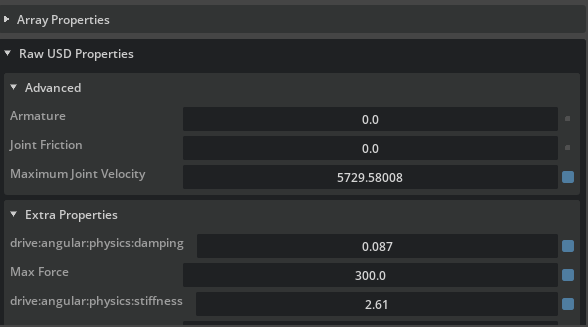
The effort_limit is the maximum effort that can be applied to the joint, set that value to the Max Force attribute of the joint drive api.
Scroll down to Raw USD Properties under the Advanced tab, set the Armature, Joint Friction attribute to the value specified in the environment definition file.
For the Maximum Joint Velocity attribute, set it to the velocity_limit value specified in the environment definition file, remember to convert it to degrees.
Note
Remember to set the joint configurations for all active joints in the robot. For example, arms, legs, etc.
Verify Joint Configuration#
To verify the joint configuration, you can play the simulation and run the following snippet in script editor to print the joint configuration.
Play the simulation
Open the script editor by clicking on Window > Script Editor.
Copy and paste the following snippet into the script editor.
Run the snippet by clicking on the Run button.
1from isaacsim.core.prims import SingleArticulation
2
3prim_path = "/h1"
4prim = SingleArticulation(prim_path=prim_path, name="h1")
5print(prim.dof_names)
6print(prim.dof_properties)
Verify that you see the console output like the following:
['left_hip_yaw', 'right_hip_yaw', 'torso', 'left_hip_roll', 'right_hip_roll', 'left_shoulder_pitch', 'right_shoulder_pitch', 'left_hip_pitch', 'right_hip_pitch', 'left_shoulder_roll', 'right_shoulder_roll', 'left_knee', 'right_knee', 'left_shoulder_yaw', 'right_shoulder_yaw', 'left_ankle', 'right_ankle', 'left_elbow', 'right_elbow']
[(0,  True, -0.42999998, 0.42999998, 1, 100.00003815, 300., 149.54197693,  5.00000191)
(0,  True, -0.42999998, 0.42999998, 1, 100.00003815, 300., 149.54197693,  5.00000191)
(0,  True, -2.34999967, 2.34999967, 1, 100.00003815, 300., 200.00009155,  4.98473263)
(0,  True, -0.42999998, 0.42999998, 1, 100.00003815, 300., 149.54197693,  5.00000191)
(0,  True, -0.42999998, 0.42999998, 1, 100.00003815, 300., 149.54197693,  5.00000191)
(0,  True, -2.86999965, 2.86999965, 1, 100.00003815, 300.,  40.00001526, 10.00000381)
(0,  True, -2.86999965, 2.86999965, 1, 100.00003815, 300.,  40.00001526, 10.00000381)
(0,  True, -3.13999987, 2.52999973, 1, 100.00003815, 300., 199.96228027,  4.99619198)
(0,  True, -3.13999987, 2.52999973, 1, 100.00003815, 300., 199.96228027,  4.99619198)
(0,  True, -0.33999997, 3.1099999 , 1, 100.00003815, 300.,  40.00001526, 10.00000381)
(0,  True, -3.1099999 , 0.33999997, 1, 100.00003815, 300.,  40.00001526, 10.00000381)
(0,  True, -0.25999996, 2.04999971, 1, 100.00003815, 300., 200.00009155,  4.98473263)
(0,  True, -0.25999996, 2.04999971, 1, 100.00003815, 300., 200.00009155,  4.98473263)
(0,  True, -1.29999983, 4.44999933, 1, 100.00003815, 300.,  40.00001526, 10.00000381)
(0,  True, -4.44999933, 1.29999983, 1, 100.00003815, 300.,  40.00001526, 10.00000381)
(0,  True, -0.86999995, 0.51999992, 1, 100.00003815, 100.,  19.99622726,  4.00000191)
(0,  True, -0.86999995, 0.51999992, 1, 100.00003815, 100.,  19.99622726,  4.00000191)
(0,  True, -1.24999988, 2.6099999 , 1, 100.00003815, 300.,  40.00001526, 10.00000381)
(0,  True, -1.24999988, 2.6099999 , 1, 100.00003815, 300.,  40.00001526, 10.00000381)]
The values in the console output are already in radians. Each row is for a joint listed in the same order as the first list.
We are interested in the last four values in each row, which are the maxVelocity, maxEffort, stiffness, damping respectively. Verify that the values match the values specified in the environment definition file.
For example, for the left_hip_yaw, the max velocity is 100.0, the max effort is 300.0, the stiffness is 150.0, and the damping is 5.0.
Note
The rigged H1 robot is available in the content browser at Isaac/Samples/Rigging/H1/h1_rigged.usd.
Summary#
This tutorial covered the following topics:
Setting initial robot position
Setting joint configuration
Verifying joint configuration