7.2.6. RTX Lidar Sensors
Isaac Sim RTX or Raytraced lidar supports both Solid State and Rotating Lidar configuration via a JSON config file. Each RTX Sensor must be attached to its own viewport to simulate properly.
Warning
Docking windows in the isaac-sim UI when an RTX Lidars simulation is running will likely lead to a crash. Please pause the simulation before re-docking the window.
7.2.6.1. Learning Objectives
In this example, we will
Have a brief introduction on how to use RTX Lidar sensors
Create a RTX Lidar sensor
Publish sensor data to ROS2 as LaserScan and PointCloud2 messages
Put it all together and visualize multiple sensors in Rviz2.
7.2.6.2. Getting Started
Important
Make sure to source your ROS 2 installation from the terminal before running Isaac Sim. If sourcing ROS 2 is a part of your bashrc then Isaac Sim can be run directly.
Prerequisites
Completed the ROS2 ROS2 Cameras tutorial.
FASTRTPS_DEFAULT_PROFILES_FILEenvironmental variable is set prior to launching sim, and ROS2 bridge is enabled.OPTIONAL: Explore the inner workings of RTX Lidar sensors by learning How They work, the RTX Lidar Nodes that use them, and how to get RTX Lidar Synthetic Data.
Completed the URDF Import: Turtlebot tutorial so that Turtlebot is loaded and moving around.
7.2.6.3. Adding a RTX Lidar ROS2 Bridge
First we need to add a lidar sensor to the robot. Go to Create -> Isaac -> Sensors -> RTX Lidar -> Rotating.
To place the synthetic lidar sensor at the same place as the robot’s lidar unit, drag the lidar prim under /World/turtlebot3_burger/base_scan. Zero out any displacement in the Transform fields inside the Property tab. The lidar prim should now be overlapping with the scanning unit of the robot.
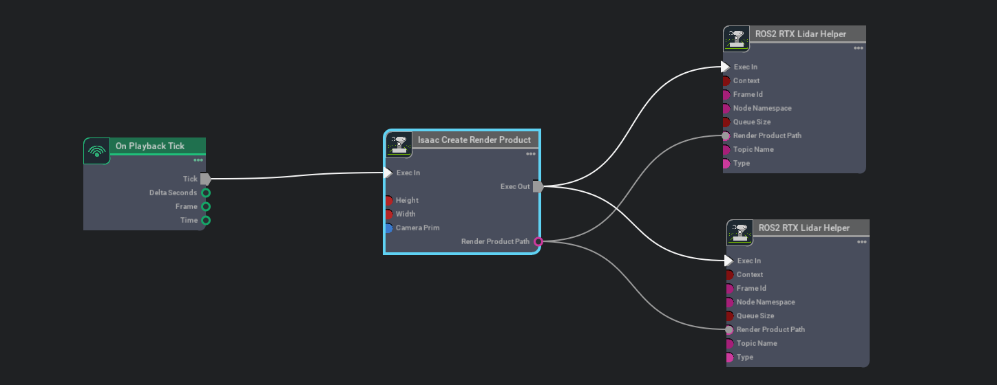
Next we connect the ROS2 bridge with the sensor output via Omnigraph Nodes. Open visual scripting editor by going to Window -> Visual Scripting -> Action Graph. Add the following nodes to this graph:
On Playback Tick: This is the node responsible for triggering all the other nodes once Play is pressed.
Isaac Create Render Product: In the input camera target prim select the RTX Lidar created in step 2.
ROS2 RTX Lidar Helper: This node will handle publishing of the laser scan message from the rtx lidar. The input render product is obtained from the output of Isaac Create Render Product in step b.
If you wish to also publish point cloud data, add another ROS2 RTX Lidar Helper node, and under input type select point_cloud and change the topic name to
point_cloud. This node will handle publishing the point cloud from the rtx lidar. The input render product is obtained from the output of Isaac Create Render Product in step b.
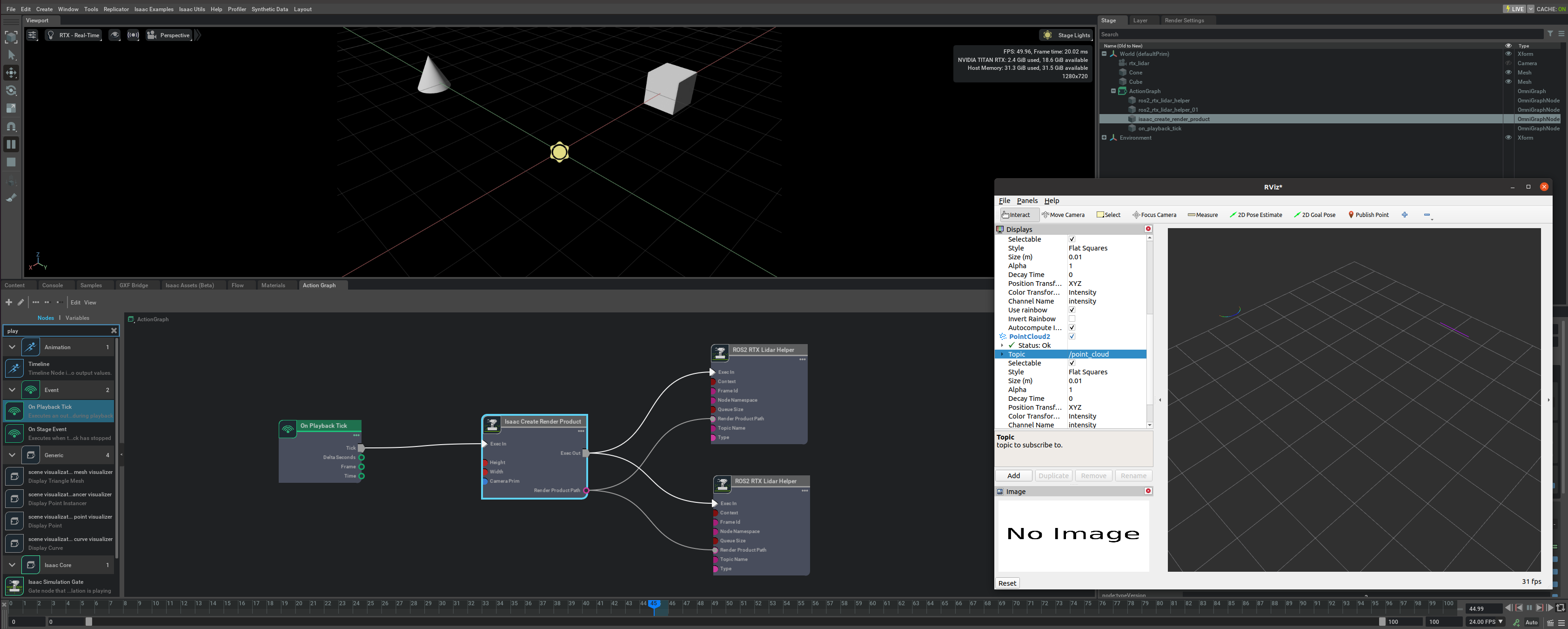
Once the graph has been set correctly, hit Play` to begin simulation. The RTX Lidar should be sending the LaserScan and PointCloud2 messages and can be visualized in RViZ.
For RViZ visualization:
Run RViZ2 (
rviz2) in a sourced terminal.The fixed frame name in Isaac Sim for the RTX lidar is set to sim_lidar, update the Rviz side accordingly.
Add LaserScan visualization and set topic to /scan
Add PointCloud2 visualization and set topic to /point_cloud
7.2.6.4. Running The Example
In a new terminal with your ROS2 environment sourced, run the following command to start rviz and show the lidar point cloud. Replace
ros2_wswithfoxy_wsorhumble_wsas appropriate.rviz2 -d <ros2_ws>/src/isaac_tutorials/rviz2/rtx_lidar.rviz
Finally, run the sample script
./python.sh standalone_examples/api/omni.isaac.ros2_bridge/rtx_lidar.py
Once the scene finishes loading you should see the point cloud for the rotating lidar sensor being simulated
7.2.6.5. RTX Lidar Script sample
While most of the sample code is fairly generic, there are a few specific pieces needed to create and simulate the sensor
We first need to create the RTX Lidar Sensor
_, sensor = omni.kit.commands.execute(
    "IsaacSensorCreateRtxLidar",
    path="/sensor",
    parent=None,
    config="Example_Rotary",
    translation=(0, 0, 1.0),
    orientation=Gf.Quatd(0.5, 0.5, -0.5, -0.5),
)
Here Example_Rotary defines the configuration for the lidar sensor. The two generic configuration files provided are located in exts/omni.drivesim.sensors.nv.lidar/data. Example_Rotary.json and Example_Solid_State.json. To switch the lidar to the example solid state configuration you can replace config=”Example_Rotary”, with config=”Example_Solid_State”.
Next, we need create a render product and attach this sensor to it
render_product = rep.create.render_product(sensor.GetPath(), [1, 1])
We can then create the post process pipeline that takes the rendered RTX Lidar data and publishes it to ROS:
sensors.get_synthetic_data().activate_node_template("RtxLidar" + "ROS2PublishPointCloud", 0, [render_product.path])
Note
You can specify an optional attributes={…} dictionary when calling activate_node_template to set node specific parameters. See the API Documentation for complete usage information.
7.2.6.6. Multiple Sensors in RViz2
To display multiple sensors in RViz2, there are a few things that are important to make sure all the messages are synced up and timestamped correctly.
Simulation Timestamp
Use Isaac Read Simulation Time as the node that feeds the timestamp into all of the publishing nodes’ timestamps.
ROS clock
To publish the simulation time to the ROS clock topic, you can setup the graph as shown in the Running ROS 2 Clock Publisher tutorial:

frameId and topicName
To visualize all the sensors as well as the tf tree all at once inside RViz, the frameId and topicNames must follow a certain convention in order for Rviz to recognize them all at once. The table below roughly describes these conventions. To see the multi-sensor example below, consult the USD asset
Isaac/Samples/ROS2/Scenario/turtlebot_tutorial.usd.Source
frameId
nodeNamespace
topicName
type
Camera RGB
(device_name):(data_type)
(device_name)/(data_type)
image_raw
rgb
Camera Depth
(device_name):(data_type)
(device_name)/(data_type)
image_rect_raw
depth
Lidar
world
laser_scan
laser_scan
TF
tf
tf
To see the rviz image below, make sure the simulation is playing. In a ROS2-sourced terminal, open with the configuration provided using the command:
ros2 run rviz2 rviz2 -d <ros2_ws>/src/isaac_tutorials/rviz2/camera_lidar.rviz. Once the Rviz window finishes loading, you can enable and disable the sensor streams inside the “Display” Panel on the left hand side.
Important
Ensure that the use_sim_time ROS2 param is set to true after running the RViz2 node.
This ensures that the RViz2 node is synchronized with the simulation data especially when RViz2 interpolates position of lidar data points.
Set the parameter using the following command in a new ROS2-sourced terminal:
ros2 param set /rviz use_sim_time true
7.2.6.7. Summary
This tutorial covered creating and using the RTX Lidar Sensor with ROS2.
This tutorial covered
Adding a RTX Lidar sensor
Adding a RTX Lidar and PointCloud ROS2 nodes.
Displaying multiple sensors in RViz2.
7.2.6.7.1. Next Steps
Continue on to the next tutorial in our ROS2 Tutorials series, ROS2 Transform Trees and Odometry, to learn how to add global and relative transforms to a TF tree.
7.2.6.7.2. Further Learning
Explore the inner workings of RTX Lidar sensors by learning How They work, the RTX Lidar Nodes that use them, and how to get RTX Lidar Synthetic Data.