2.7. OmniGraph
OmniGraph is Omniverse’s visual programming framework. It provides a graph framework that can easily connect functions from multiple systems inside Omniverse. It is also a compute framework that allows for highly customized nodes so that users can integrate their own functionality into Omniverse and automatically harness the efficient computation backend.
Inside Omniverse Isaac Sim, OmniGraph is the main engine behind the Replicators, ROS and ROS2 bridges, access to many sensors, controllers, external input/output devices, UI, and much more. The purpose of this tutorial is giving you a fast introduction into the world of visual programming via OmniGraph. We highly recommend you to checkout the much more in-depth documentation on OmniGraph, for it is a key component in Omniverse Kit.
2.7.1. Learning Objectives
This tutorial details build an action graph to control a robot in Omniverse Isaac Sim, specifically, the Jetbot. The goal of this tutorial is to give you a fast introduction to using Action Graphs in Omniverse Isaac Sim.
10-15 Minute Tutorial
2.7.2. Getting Started
Prerequisites
Review Isaac Sim Interface prior to beginning this tutorial.
Check out Assemble a Simple Robot for details on how you setup your own robot.
2.7.3. Setting up the stage
On a new stage, start by right clicking and selecting create > Physics > Ground Plane.
Next, use the content browser to navigate to Isaac/Robots/JetBot and click and drag jetbot.usd onto the stage. Position the jetbot just above the ground plane. When completed, the jetbot should be under
/World/jetbot in the context tree and the stage should look similar to this
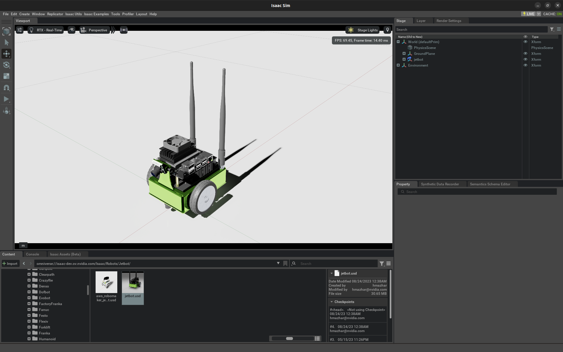
Jetbot on the stage
Note
Click play! You should see jetbot fall and land on the stage. Click stop before continuing.
Depending on your default render settings, the camera of the jetbot may have a placeholder mesh (it looks like a gray Television camera). To hide these meshes, click on the 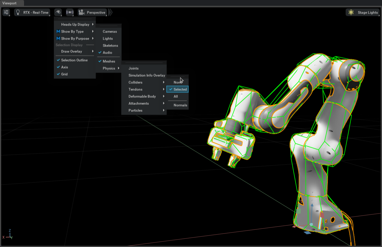 icon in the viewports,
and then select
icon in the viewports,
and then select Show By Type --> Cameras to hide the placeholder mesh.
2.7.4. Building the graph
Select Window -> Visual Scripting -> Action Graph from the dropdown menu at the top of the editor. The Graph Editor
will appear in the same pane as the Content browser. Click New Action Graph to open an empty graph. Type controller in the search bar
of the graph editor, and drag an Articulation Controller and a Differential Controller onto the graph.
The Articulation Controller applies driver commands (in the form of force, position, or velocity) to the specified joints
of any prim with an articulation root. To tell the controller which robot it’s going to control, first select the Articulation Controller node in the graph and open up the property pane. You can either keep usePath checked and type in the path to the robot /World/jetbot in the robotPath, or you can uncheck usePath and then
click Add Targets near the top of the pane for input:targetPrim, and select jetbot in the pop up window.
The Differential Controller computes drive commands for a two wheeled robot given some target linear and angular velocity. Like the
Articulation Controller, it also needs to be configured. Select the Differential Controller node in the graph, and then in the
properties pane, set the wheelDistance to 0.1125, the wheelRadius to 0.03, and maxAngularSpeed to 0.2.
When finished, the properties of the controllers should look like the following
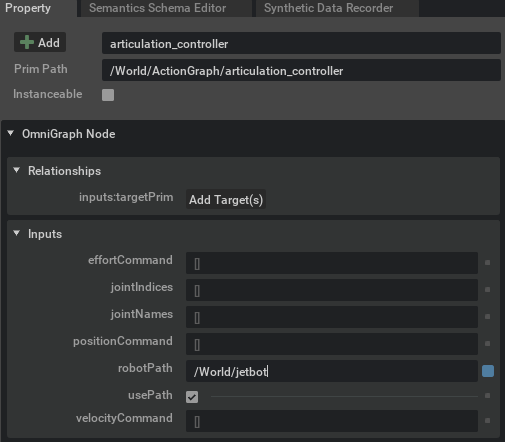
Articulation Controller
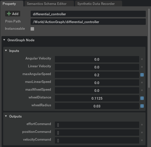
Differential Node
The Articulation Controller also needs to know which joints to articulate. It expects this information in the form of a list of tokens or index
values. Each joint in a robot has a name and the jetbot has exactly two. Verify this by examining the jetbot in the stage context tree. Within /World/jetbot/chassis
are two revolute physics joints named left_wheel_joint and right_wheel_joint.
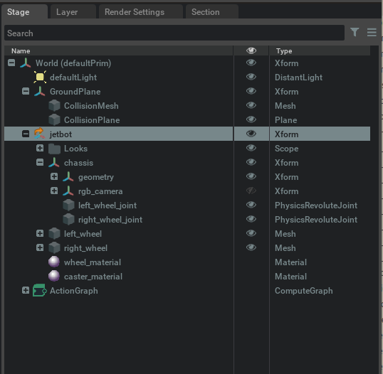
Stage Tree
Type token into the search bar of the graph editor and add two Constant Token nodes to the graph.
Select one, and set it’s value to left_wheel_joint in the properties pane. Repeat this for the other constant
token node, but set the value to right_wheel_joint. Type make array into the search bar of the graph editor and add
a Make Array node to the graph. Select the Make Array node and click on the + icon in the inputs section of the property pane menu to add a second input. Set the arraySize to 2 as well, and then set the input type
to token[] from the dropdown menu in the same pane. Finally, connect the constant token nodes to A and B of the Make Array node, and then the output of that node to the Joint Names input
of the Articulation Controller node.
The last node is the event node. Search for playback in the search bar of the graph editor and add an On Playback Tick node to the graph. This node will emit
an execution event for every frame, but only while the simulation is playing. Connect the Tick output of the On Playback Tick node to the
Exec In input of both controller nodes. Connect the Velocity Command output of the differential controller to the Velocity Command input
of the articulation controller. When completed, the graph should look similar to this…
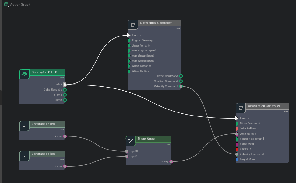
Simple differential control for the JetBot
Press the play button and select the Differential Controller Node in the graph. Click and drag on either the angular or linear velocity values in the
properties pane to change it’s value (or just click and type in the desired value).
Controlling the JetBot using the differential controller
Note
As an exercise for the reader, explore the available OmniGraph nodes and try to setup a graph to control the jetbot with the keyboard! The graph below is an example graph for controlling the jetbot with a keyboard.
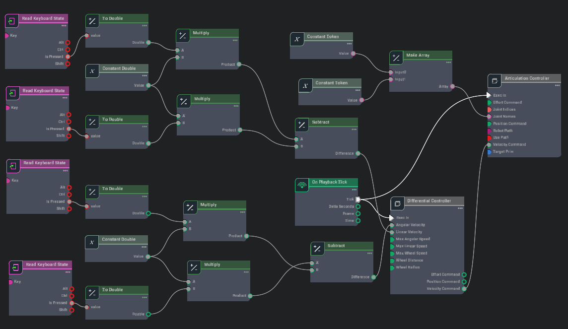
Keyboard control Actiongraph for the JetBot
2.7.5. Summary
This tutorial covered the following topics:
Setting up a stage with a simple robot
Using OmniGraph to construct simple interfaces to a robot
2.7.5.1. Further Learning
More in-depth concepts in OmniGraph
Examples for using OmniGraph to connect input devices: OmniGraph: Input Devices
Examples for composing OmniGraph via Python scripting: OmniGraph: Python Scripting
Examples for writing custom python nodes: Omnigraph: Custom Python Nodes